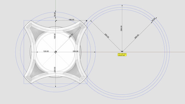
The measurements for the floor plan of the modern ionic capital are given in https://pixelfed.social/p/Splines/807782440025967685 with further links to relevant pages in #Scarlata's book at the bottom.
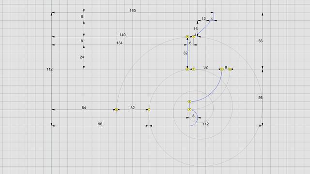
I won't bore you with the bottom portion of the modern #capital because it is very similar to that of the classic capital shown in https://pixelfed.social/p/Splines/792124787573855518. A significant difference is that the bottom #ovolo is shorter, with a total height of 32 units instead of 40
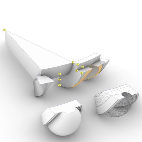
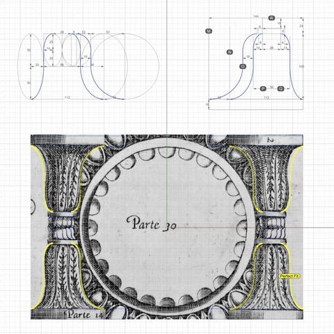
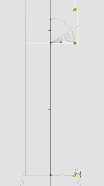
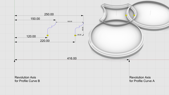
For the cap, we need two identical copies of a single profile curve that is 30 units wide and 48 units tall. The curves marked by A and B in the diagram are oriented in the same direction and are spaced 100 units from each other.
The bottom of profile curve A lines up with the neck of the #columnShaft at 120 units from the column axis. The revolution axis for this curve is located at 416 units from the column axis at the center of the largest circle in the floor plan.
We #revolve profile curve A full circle about its revolution axis. Then, we #rotate the resulting surface about the column axis to get 4 identical copies.
We revolve profile curve B full circle about the column axis. Then, we trim the resulting surface along with the 4 others at each intersection to get the side and corner surfaces for the cap of the capital.
We #join the trimmed surfaces, cap #planarHoles to convert them into a closed solid, and verify that the resulting solid is #airtight with no #nakedEdges and no #nonManifoldEdges.
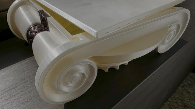
The cap is in the correct final orientation. The volutes will be at 45° angles, but when we construct them, it will be easier to rotate the whole plan 45° so that the #volute #spiral is on the XZ plane.

Splines (@[email protected])
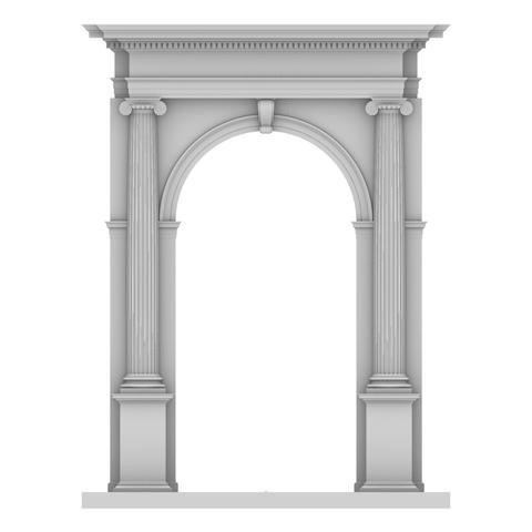
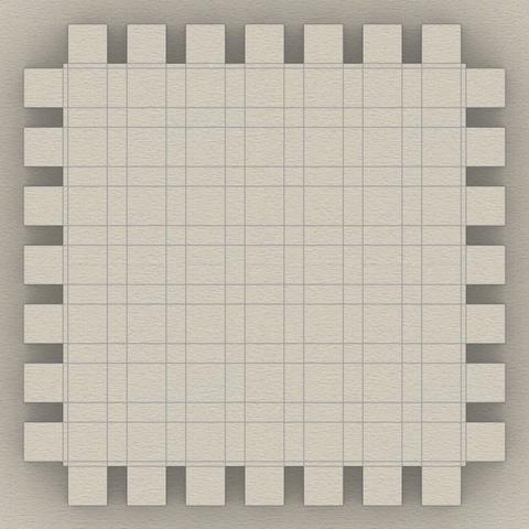
Plan for the #ModernIonicCapital If the design in https://pixelfed.social/p/Splines/807569519962747338 looks daunting, let me assure you it is far simpler than the work that went into the reconstruction of just the #scroll for the #classicIonicCapital. Be sure to check out #MileStone4 at https://pixelfed.social/p/Splines/795361973789834465. With the modern #IonicCapital, the designers went back to the basics of using just straight lines and circular arcs to define the geometry of the essential elements of the capital. No #braids, #keystones, or #modillions, and no #helix curves or #sinusoids. We start the floorplan for the modern ionic capital with a circle of radius 5/6 of µ (120 when µ = 144) which marks the neck of the #columnShaft. Tangent to this circle is a large circle of radius 296 units centered on the X axis exactly 416 units from the column axis. This is the circle that marks the curve of the #abacus, which is always tangential to the column shaft at the neck. This circle also marks the curved faces of the interior portion of the #volute wedge. Without the raised volute spirals, the interior wedge appears flush with the abacus as they follow the same circular arc. Concentric to this large circle is another circle with a radius of 280 units to mark the extent of the raised volute spirals which are 16 units thick. Another concentric circle of radius 266 units marks the outer edge of the top of the capital. The gap between the outermost large circle and the innermost concentric circle is 30 units, and that is reflected in another pair of circles centered on the column axis with radius of 250 units and 220 units to define the four corners. The capital footprint fits in a square 396 units wide — or 24.75 parts horizontally from axis, per #Scarlata in https://babel.hathitrust.org/cgi/pt?id=mdp.39015031201190&view=1up&seq=45. Use this with the sketch in https://babel.hathitrust.org/cgi/pt?id=mdp.39015031201190&view=1up&seq=142