#Milestone9 - #ArcadeIntercolumniation #Keystone and #Modillion

#Arch without Pedestal https://pixelfed.social/p/Splines/803615973439041638

#Arch with #Pedestal and Keystone https://pixelfed.social/p/Splines/804537414363507454

#Keystone and #Dentil Details https://pixelfed.social/p/Splines/804548474524642209

#Modillion Details https://pixelfed.social/p/Splines/805587292338863257

#ModernEntablature with Detail https://pixelfed.social/p/Splines/805607059171193759

#Milestone8 - #SimpleIntercolumniation https://pixelfed.social/p/Splines/803106316515798367

#Milestone7 - Complete #IonicOrder https://pixelfed.social/p/Splines/800050647761776920

#Milestone6#Braids #3StrandBraids https://pixelfed.social/p/Splines/799602946527813102

#Milestone5#EggsAndDarts https://pixelfed.social/p/Splines/797069447808333887

#Milestone4#IonicScroll https://pixelfed.social/p/Splines/795361973789834465

#Milestone3#IonicColumn https://pixelfed.social/p/Splines/792803978865652429

#Milestone2 — Classic #IonicEntablature https://pixelfed.social/p/Splines/791021871062069787

#Milestone1#IonicPedestal https://pixelfed.social/p/Splines/790752092700055739
Splines (@Splines@pixelfed.social)

#Arcade #Intercolumniation without #Pedestal In https://pixelfed.social/p/Splines/803089629244302486, we saw #simpleIntercolumniation, also known as #Architravato. Roman architects combined columns with walls thick enough to bury half of the column width inside the walls and added arches to them for better load distribution. An arcade (multiple arches) can be run in series along a single wall, or in parallel to form a walkway. They can also be combined in both series and parallel configurations, perhaps the most famous of which is the #Colosseum in Rome. In the Colosseum, the outer walls follow an elliptical curve (even though it looks circular from the outside), and it has multiple tiers of arches in series. The interior has arches in concentric passageways in the lower tiers giving it a lattice-like design. Because arches distribute the load from above, they allow for wider intercolumniation. The rules for #ArcadeIntercolumniation differ depending on whether the columns have pedestals or not. Besides the arch itself, which is part of the wall, the figure shows some new architectural elements. The narrow part of the wall immediately behind a column is known as a #pier. The visible face of a pier between a column and the opening under the arch is known as #alette. The base of the pier has a molding, the flat part of which has the same height as the column base (µ) while the rest follows the #fillet and #cavetto or #conge of the #shaft. As we move up the pier, there is a horizontal molding known as #impost just below where the arc of the arch starts. The impost wraps around on the sides of the pier. Around the arc is a circular molding known as #archivolt, the bottom portion of which has a #fascia that is aligned with the face of the wall. The wall itself extends all the way to the top of the #entablature. It is worth noting that the entablature is repeated on the wall. It doesn't end at the columns and has two "outside" corners and one "inside" corner.

Pixelfed
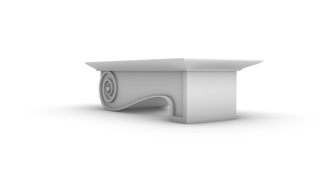
#Modillion for the #ModernIonicEntablature

In https://pixelfed.social/p/Splines/790782316675150160 , I mentioned that there are two variations of the #IonicEntablature — a classic version that we saw in https://pixelfed.social/p/Splines/804548474524642209, and a modern version that has a new feature called #modillions, which are projecting brackets under the #corona of the #cornice. Note that, "modern" is a relative term. For designs that are more than 2000 years old, even an alteration hundreds of years ago would qualify as modern.

The modillion design continues a similar pattern but not identical to that of a #keystone. The measurements can be found in https://babel.hathitrust.org/cgi/pt?id=mdp.39015031201190&view=1up&seq=45 from which you can surmise that the length is 130 units (based on µ = 144) and the height is 36 units excluding the flamboyant #cymaReversa. The depth is not given, but can be derived from the sketch in https://babel.hathitrust.org/cgi/pt?id=mdp.39015031201190&view=1up&seq=141.

The measurements for the cymaReversa are listed between the corona and medallions, but its #profileCurve is attached to the modillion, not to the corona. Like #dentils, we attach modillions separately to the entablature. The dentils are still there with the same square footprint and same interdental spacing, but they are shorter to make room for the modillions above.

The original #volute that forms the basis of the modillion design is µ = 144 wide (including #arcZero) and 128 tall. Since the modillion height divides evenly into µ, I used that orientation for constructing the modillion, creating a box 144 units wide and 520 units tall. After construction, I scaled it to 1/4 to get 36 x 130 units, and then rotated it 90°.

The length of 520 was divided into 128*3.5 = 448 for the curved portion (which aligns with the wall) and 72 for the straight portion, which faces the front. Try to recreate it on your own first, and if you need help, just ask me.
Splines (@Splines@pixelfed.social)

There are two variations of the #IonicEntablature. The classic variation has #dentils, which are teeth-like structures shown here above the #frieze. The modern version has #modillions, which are projecting brackets under the #corona of the #cornice. Well, "modern" is a relative term. For designs that are more than 2000 years old, even an alteration 1000 years ago would qualify as modern. Although the sketch shows the #entablature with a square footprint, in practice, it runs the entire length of a #colonnade (multiple columns) or an #arcade (multiple arches). #CAD construction of the entablature is very similar to that of a #pedestal. The first step is to consult #Vignola's #RegolaArchitettura for the visual appearance, and then consult #Scarlata's #PracticalArchitecture for #VignolaProportions in tabular form. It is convenient to create a spreadsheet to convert the measurements given in Scarlata's book from module "parts" to your own model units based on your choice of value for the module parameter µ. Armed with these measurements, it is time to plot the points and draw the #primaryProfileCurves on our standard 2D grid with minor grid lines 8 units apart and major grid lines 32 units apart. In the first pass, skip the dentils and draw the profile curves for the rest of the moldings. Just as with the pedestal, I will show the macro-level plan as well as the detail plan. So, you don't have to go to Scarlata's book, but you know it's there if you want to. I will show the dentil arrangement in a subsequent post. Based on µ = 144, the classic Ionic entablature is 648 units (36 parts, or 4.5*µ) tall. Of this, the #architrave at the bottom is 180 units (10 parts, or 1.25*µ) tall, the frieze in the middle is 216 units (12 parts, or 1.5*µ) tall, and the cornice at the top is 252 units (14 parts, or 1.75*µ) tall.

Pixelfed
#Milestone8 - #SimpleIntercolumniation

Floor Plan of archetypal Greek Temple https://pixelfed.social/p/Splines/803021258359555093

Front and back #intercolumniation https://pixelfed.social/p/Splines/803076419096100108

Side intercolumniation https://pixelfed.social/p/Splines/803089629244302486

#Milestone7 - Complete #IonicOrder https://pixelfed.social/p/Splines/800050647761776920

#Milestone6#Braids #3StrandBraids https://pixelfed.social/p/Splines/799602946527813102

#Milestone5#EggsAndDarts https://pixelfed.social/p/Splines/797069447808333887

#Milestone4#IonicScroll https://pixelfed.social/p/Splines/795361973789834465

#Milestone3#IonicColumn https://pixelfed.social/p/Splines/792803978865652429

#Milestone2 — Classic #IonicEntablature https://pixelfed.social/p/Splines/791021871062069787

#Milestone1#IonicPedestal https://pixelfed.social/p/Splines/790752092700055739
Splines (@Splines@pixelfed.social)

Floor Plan of https://pixelfed.social/p/Splines/802974815166948953 showing #intercolumniation. Greek architects classified temples and public buildings based on number of columns in front, number of columns in both front and rear, as well as interior columns. The simplest buildings are those with walls on three sides, and partial walls called #antae (singular #antis) in front, flanked by just two columns. Buildings with 2 columns in front are #distyle, 4 columns are #tetrastyle, 6 are #sexastyle, 8 #octastyle, 10 #decastyle, and those with 12 columns would be #dodecastyle. The classifications are refined further. Those with 2 columns flanked by antae are called #inAntis. These never have any columns in the back or sides. Tetrastyle buildings with 4 columns only in the front are #prostyle, and those with 4 columns in both front and back are #amphiProstyle. Sexastyle buildings like those in the previous post are called #peripteral. Octastyle buildings with densely arranged internal rows are called #dipteral, and when some internal columns are removed, the sparse structure is called #pseudoDipteral. Decastyle buildings are also called #hypaethral. With 10 columns in front and rear, these are noteworthy for their width. In fact, they are so wide that they don't have a roof in the middle, which is open to the sky. Only the four sides have roofs supported by columns. In addition to the number columns, there is a further classification based on #intercolumniation. #Vitruvius described five classes of temples, designated as follows: "#pycnostyle, with the columns close together; #systyle, with the intercolumniations a little wider; #diastyle, more open still; #araeostyle, farther apart than they ought to be; #eustyle, with the intervals apportioned just right." The building in my previous post (shown without walls) has 6 columns in front and back — so, it is sexastyle. It is also known as a "Peripteral Eustyle," with column "intervals apportioned just right."

Pixelfed
Splines (@Splines@pixelfed.social)

#Milestone 6 — #Braids #3StrandBraids #Sinusoid from #Helix https://pixelfed.social/p/Splines/797893262102038801 Braid Geometry https://pixelfed.social/p/Splines/797916882329430160 Braid Strand https://pixelfed.social/p/Splines/798252244743520392 Braid Assembly https://pixelfed.social/p/Splines/799340150182400358 Braid #FlowOnSurface https://pixelfed.social/p/Splines/799514176049543252 #Milestone 5 — #EggsAndDarts https://pixelfed.social/p/Splines/797069447808333887 #Milestone 4 — #IonicScroll https://pixelfed.social/p/Splines/795361973789834465 #Milestone 3 — #IonicColumn https://pixelfed.social/p/Splines/792803978865652429 Milestone 2 — Classic #IonicEntablature https://pixelfed.social/p/Splines/791021871062069787 Milestone 1 — #IonicPedestal https://pixelfed.social/p/Splines/790752092700055739

Pixelfed
#Milestone6#Braids #3StrandBraids

#Sinusoid from #Helix https://pixelfed.social/p/Splines/797893262102038801

Braid Geometry https://pixelfed.social/p/Splines/797916882329430160

Braid Strand https://pixelfed.social/p/Splines/798252244743520392

Braid Assembly https://pixelfed.social/p/Splines/799340150182400358

Braid #FlowOnSurface https://pixelfed.social/p/Splines/799514176049543252

#Milestone5#EggsAndDarts https://pixelfed.social/p/Splines/797069447808333887

#Milestone4#IonicScroll https://pixelfed.social/p/Splines/795361973789834465

#Milestone3#IonicColumn https://pixelfed.social/p/Splines/792803978865652429

#Milestone2 — Classic #IonicEntablature https://pixelfed.social/p/Splines/791021871062069787

#Milestone1#IonicPedestal https://pixelfed.social/p/Splines/790752092700055739
Splines (@Splines@pixelfed.social)

#Braids #3StrandBraids After creating the two #helix curves as described in https://pixelfed.social/p/Splines/797732962403957263, switch to the front view and #project the smaller blue helix on the vertical "wall" of the XZ plane. Hide the original helix. Then switch to the top view and project the larger magenta helix on the "ground" or XY plane and hide the original helix. Now compare the figure in this post with that in the previous post. Both curves have now been #flattened from 3D helix to 2D #sinusoid. When viewed from the front (top-left portion of the diagram), the blue curve is still visible as a #sinusoidal waveform but the magenta appears as a straight line flattened on the ground. When viewed from the top, the magenta curve is still visible as a sinusoid but the blue appears as a straight line clinging to the vertical wall. In the view from side (bottom-left portion of diagram), neither waveform is apparent, and both curves appear as perpendicular straight lines. Only in the perspective view you can see both waveforms, but even here it is clear that they are both flat 2D curves oriented perpendicular to each other in 3D space. Our goal is to convert these two flat sinusoids back into a single composite 3D curve that shows the smaller waveform in the front view and larger one in the top view. In acoustics, a sinusoid represents a pure tone with a single frequency. The tone varies with frequency and its perceptibility varies with amplitude. Musicians and people familiar with acoustic physics will immediately recognize that the blue curve has twice the frequency (or pitch) of the magenta curve, while the magenta curve has twice the amplitude (loudness) of the blue curve. We can divide the period or wavelength into phases. For the blue one, we divide the wavelength into 4 phases of 6 units each and shift the magenta curve left by that amount. Later, we will divide the magenta one into 3 phases — one for each strand, and shift each rightward by that.

Pixelfed
Splines (@Splines@pixelfed.social)

See https://pixelfed.social/p/Splines/796798349526747214 and https://pixelfed.social/p/Splines/796786779066451143 for detail. Just like #ArcZero in the #spiral for the #IonicVolute, the plan for #EggsAndDarts starts out larger than what is eventually used. The outermost frame is 7.5 parts or 60 units tall (from A to D), and 5 parts or 40 units wide when µ = 144. The innermost frame is 6 parts or 48 units tall (from B to C), and 4 parts or 32 units wide. The height and width for both inner and outer are in 3:2 ratio. The difference in height is also split in the ratio 3:2. So, the gap between A and B as 12*2/5 = 4.8, and the gap between C and D as 12*3/5 = 7.2. We then divide both of these gaps in 5 equal segments shown by the dots between them. Create an ellipse to fill the outer frame, and another to fill in the inner frame. Then interpolate them to create 4 more through the dots, only to delete the 3rd ellipse. This gives us the 5 #rails for sweeping the rim of the egg. Create circles perpendicular to and touching adjacent pairs of rails, and then #sweepTwoRails using the circles to get the rim shown in the top-right. The red cutting plane marks tentative slicing for eggs. The bottom left image shows a convex egg created with an #ellipsoid that is 48 units tall, 32 units wide, and 32 units deep. This is equivalent to #revolving the innermost ellipse around its major axis. Only half of this egg is above the oval slab. The bottom right image shows the concave variant which is created by performing a #booleanDifference between the oval slab and the round egg created above. The top portion of the egg is removed in the concave variant, but the convex variant must still account for the bulge of a fully round egg. As such, the slab heights of the convex and concave variant are different. I will show the measurements later. To create the slabs for the convex and concave variants, #extrude the outermost ellipse according to their measurements and #cap #planarHoles.

Pixelfed
Splines (@Splines@pixelfed.social)

#IonicVolutes are the sinews of #IonicScrolls. Without #volutes, there would be scrolls, but not #Ionic Scrolls. Each scroll starts with a volute in front and is modulated by as many as six volutes of different shapes and sizes as it reaches the back, with the scroll surface tightly hugging the volutes at each contact point in ALL 3 dimensions. This is a key point to remember before we start #reverseEngineering the first #primaryProfileCurves from old image scans. This diagram shows the #scaffolding we will construct using straight lines and rectangles, first in 2 dimensions, then place them front-to-back in 3 dimensions using precise markers, and finally scale and superimpose the volutes on this scaffolding. All of this will be done before we derive the primary profile curves from the image scans. How did I know about this scaffolding? I didn't. It is not documented anywhere that I'm aware of. I developed this after years of striving to derive the correct shape, and I hope that there are people who can still "see" things I might have missed and help improve the design. So, the actual process went like this: I drew outlines from 2D image scans in the top view, getting close to #Vignola's detailed sketches. Then, I did the same thing with image scans in the side view, and I found that the designs didn't line up. After several iterations, I got the designs to line up in both views, and it was obvious that the bell shape of the scroll would follow the large volute in the front. So, I used the large volute as a "rail" and tried to sweep the primary profile curves on one rail. Big mistake! The undulating shapes of the primary profile curves wobbled wildly on the single rail — The middle, 3/4, and back of the scroll were twisted out of shape! Instead of trying to #sweepOneRail, I decided to clamp down wobbling with another operation called #sweepTwoRails, using volutes at both front and back ends as rails with less wobbling. You will need a #CAD tool to practice.

Pixelfed
Splines (@Splines@pixelfed.social)

#IonicColumn #VignolaBase and #AtticBase #CAD Plans Both #Vignola base and #Attic base have the same square footprint of 400 units x 400 units. The #plinth for both is 48 units (6 parts, or µ/3) tall, and the total height for both is 144 units (18 parts, or exactly µ). As such, they are easily interchangeable. In the Vignola variant, we start at the plinth with a #fillet 2 units tall and a classic #scotia 18 units tall gouging out part of the fillet. Then there is another fillet 2 units tall, followed by two #reeds, each 8 units tall, followed by another classic scotia as described above. This is followed by yet another fillet 2 units tall and topped off with a #torus 40 units tall. A Torus is the same as a reed, except larger. When we reach the neck of the shaft, we will see another molding called #Astragal which has the same profile as reed and torus, but sits in the middle in size. Think of reed, astragal, and torus as small, medium, and large of the same profile. The modern Attic variant is more elegant with fewer moldings. It also gives the impression of more heft for more stately columns. It starts at the plinth with a torus 36 units tall, followed by a fillet 4 units tall, followed by a modern scotia 24 units tall, followed by another fillet 4 units tall, and topped off with another torus 28 units tall. As in the construction of #IonicEntablature [https://pixelfed.social/p/Splines/791013152244518907], split the construction of the #columnBase into two steps. Just as we extruded #dentils separately, we extrude the plinth separately. First draw a square 400x400 in the top view. Then extrude the square 48 units in the front view. For the rest of the base, we need a new 3D operation — #revolve around an axis. Instead of extruding the #primaryProfileCurve, we revolve it around the #columnAxis, and cap the #planarHoles on both ends before performing a #booleanUnion with the plinth. Finally check edges of the solid for #nakedEdges and #nonManifoldEdges.

Pixelfed
#IonicColumn #VignolaBase and #AtticBase #CAD Plans

Both #Vignola base and #Attic base have the same square footprint of 400 units x 400 units. The #plinth for both is 48 units (6 parts, or µ/3) tall, and the total height for both is 144 units (18 parts, or exactly µ). As such, they are easily interchangeable.

In the Vignola variant, we start at the plinth with a #fillet 2 units tall and a classic #scotia 18 units tall gouging out part of the fillet.

Then there is another fillet 2 units tall, followed by two #reeds, each 8 units tall, followed by another classic scotia as described above.

This is followed by yet another fillet 2 units tall and topped off with a #torus 40 units tall. A Torus is the same as a reed, except larger. When we reach the neck of the shaft, we will see another molding called #Astragal which has the same profile as reed and torus, but sits in the middle in size. Think of reed, astragal, and torus as small, medium, and large of the same profile.

The modern Attic variant is more elegant with fewer moldings. It also gives the impression of more heft for more stately columns. It starts at the plinth with a torus 36 units tall, followed by a fillet 4 units tall, followed by a modern scotia 24 units tall, followed by another fillet 4 units tall, and topped off with another torus 28 units tall.

As in the construction of #IonicEntablature [https://pixelfed.social/p/Splines/791013152244518907], split the construction of the #columnBase into two steps.

Just as we extruded #dentils separately, we extrude the plinth separately. First draw a square 400x400 in the top view. Then extrude the square 48 units in the front view.

For the rest of the base, we need a new 3D operation — #revolve around an axis. Instead of extruding the #primaryProfileCurve, we revolve it around the #columnAxis, and cap the #planarHoles on both ends before performing a #booleanUnion with the plinth. Finally check edges of the solid for #nakedEdges and #nonManifoldEdges.
Splines (@Splines@pixelfed.social)

This sketch shows the arrangement of #dentils in the classic variation of the #IonicEntablature. It shows the full layout, but most of the top is obscured by the top portion of the #cornice. Only the outside square shapes are actually visible. Each #dentil has a square "footprint" that is 4 parts by 4 parts (32*32 units) and is 6 parts (48 units) tall. The spacing between each dentil is 2 parts (16 units). Dentils project 4 parts (or 32 units) from the face of the #fascia on which they rest. Each face of the fascia has 7 dentils with the middle dentil laterally centered and directly in front of the column axis. The 2 side dentils are on side faces, and that is apparent in the darker shading in the sketch at https://pixelfed.social/i/web/post/790782316675150160. Take the time to reconcile this with the numbers listed in #Scarlata's #PracticalArchitecture. The 3D reconstruction from the #primaryProfileCurves is very similar to that of the #IonicPedestal, with #extrusion, #mitering, #joining, and #capping planar holes as described in https://pixelfed.social/i/web/post/790645054230337543 — just set the dentils aside, for now. Once you have capped the #planarHoles to get a solid, analyze the edges of the solid in the #CAD program for #nakedEdges and #nonManifoldEdges. Then, extrude the dentils outline (in the top view) to a height of 48 units (in the front view). Now perform a #booleanUnion of the two solid shapes to get the complete #entablature. Finally, check the edges of the solid in the #CAD program AGAIN for #nakedEdges and #nonManifoldEdges. With this, we have finished two of the three main components of the #IonicOrder. There's a modern version of the Ionic entablature with #modillions, which I will describe later. Next, we move on to the biggest, most conspicuous part of the order — the #IonicColumn.

Pixelfed
This sketch shows the arrangement of #dentils in the classic variation of the #IonicEntablature. It shows the full layout, but most of the top is obscured by the top portion of the #cornice. Only the outside square shapes are actually visible.

Each #dentil has a square "footprint" that is 4 parts by 4 parts (32*32 units) and is 6 parts (48 units) tall. The spacing between each dentil is 2 parts (16 units).

Dentils project 4 parts (or 32 units) from the face of the #fascia on which they rest.

Each face of the fascia has 7 dentils with the middle dentil laterally centered and directly in front of the column axis. The 2 side dentils are on side faces, and that is apparent in the darker shading in the sketch at https://pixelfed.social/i/web/post/790782316675150160. Take the time to reconcile this with the numbers listed in #Scarlata's #PracticalArchitecture.

The 3D reconstruction from the #primaryProfileCurves is very similar to that of the #IonicPedestal, with #extrusion, #mitering, #joining, and #capping planar holes as described in https://pixelfed.social/i/web/post/790645054230337543 — just set the dentils aside, for now.

Once you have capped the #planarHoles to get a solid, analyze the edges of the solid in the #CAD program for #nakedEdges and #nonManifoldEdges.

Then, extrude the dentils outline (in the top view) to a height of 48 units (in the front view).

Now perform a #booleanUnion of the two solid shapes to get the complete #entablature.

Finally, check the edges of the solid in the #CAD program AGAIN for #nakedEdges and #nonManifoldEdges.

With this, we have finished two of the three main components of the #IonicOrder. There's a modern version of the Ionic entablature with #modillions, which I will describe later.

Next, we move on to the biggest, most conspicuous part of the order — the #IonicColumn.
Splines (@Splines@pixelfed.social)

There are two variations of the #IonicEntablature. The classic variation has #dentils, which are teeth-like structures shown here above the #frieze. The modern version has #modillions, which are projecting brackets under the #corona of the #cornice. Well, "modern" is a relative term. For designs that are more than 2000 years old, even an alteration 1000 years ago would qualify as modern. Although the sketch shows the #entablature with a square footprint, in practice, it runs the entire length of a #colonnade (multiple columns) or an #arcade (multiple arches). #CAD construction of the entablature is very similar to that of a #pedestal. The first step is to consult #Vignola's #RegolaArchitettura for the visual appearance, and then consult #Scarlata's #PracticalArchitecture for #VignolaProportions in tabular form. It is convenient to create a spreadsheet to convert the measurements given in Scarlata's book from module "parts" to your own model units based on your choice of value for the module parameter µ. Armed with these measurements, it is time to plot the points and draw the #primaryProfileCurves on our standard 2D grid with minor grid lines 8 units apart and major grid lines 32 units apart. In the first pass, skip the dentils and draw the profile curves for the rest of the moldings. Just as with the pedestal, I will show the macro-level plan as well as the detail plan. So, you don't have to go to Scarlata's book, but you know it's there if you want to. I will show the dentil arrangement in a subsequent post. Based on µ = 144, the classic Ionic entablature is 648 units (36 parts, or 4.5*µ) tall. Of this, the #architrave at the bottom is 180 units (10 parts, or 1.25*µ) tall, the frieze in the middle is 216 units (12 parts, or 1.5*µ) tall, and the cornice at the top is 252 units (14 parts, or 1.75*µ) tall.

Pixelfed