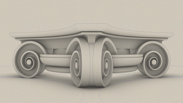
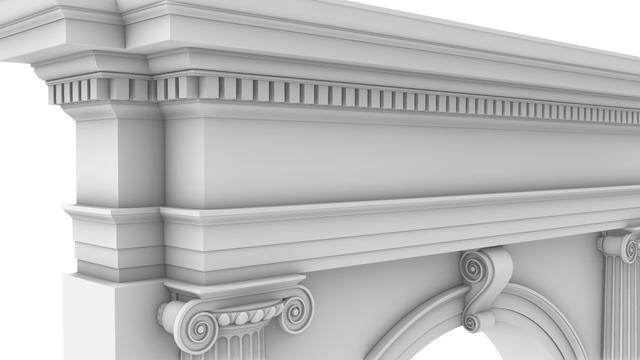
More details on alignment of various elements in the classic
#IonicCapital in
https://pixelfed.social/p/Splines/800161382832200305
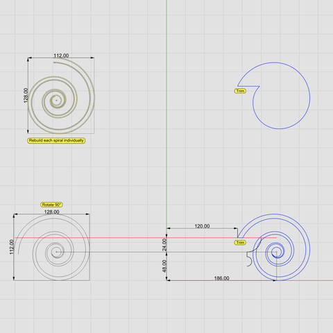
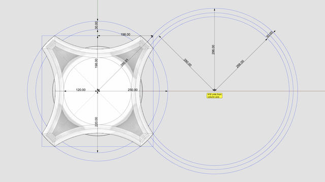
Here, we zoom in on the two
#braids assemblies — the straight vertical one on the side of the
#capital and the curved one around the neck of the
#scroll.
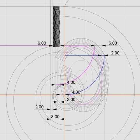
In this diagram, the magenta curve for the curved braids is extended on both sides to show the full original
#modulatingSpiral for the rear end of the scroll.
The diagram also shows the lines tangential to the full modulating spiral. As previously mentioned, the top tangent is coincident with the magenta line for the top of the
#ovolo. Additionally, the bottom tangent is tangential to the bottom of the
#eye of the
#volute.
The right tangent of the modulating spiral bisects the curved braid assembly with 4 units on either side of the tangent, and the magenta
#tectonic surface further bisects the gap between that tangent and the "underside" of the braids assembly on the right.
The top gap between magenta and blue arcs is split into 6 units and 2 units — same as the proportion of the braids channel above and below the tectonic surface.
Moving on to the bottom of the vertical braids assembly, follow the lines that divide the depth of the assembly (8 units) into 4 portions. The leftmost 2 units are, of course, sub-surface, buried inside the vertical wall of the capital.
The middle line is tangential to the left side of the eye of the volute. The next line, moving right, is tangential to the left side of the modulating spiral. The rightmost line is tangential to the outer surfaces of both braids assemblies, as already mentioned in the previous post.
Note the symmetry of 2 units and 4 units near the left side of the eye.
These meticulous details are what I call pure
#poetryInGeometry.
In
https://pixelfed.social/p/Splines/792499765146596723, I wrote that Dürer's approximation of
#logarithmicSpirals comes close, but still doesn't fit the measurements of the
#IonicCapital. This is why.