#ModernIonicCapital #Volute Construction

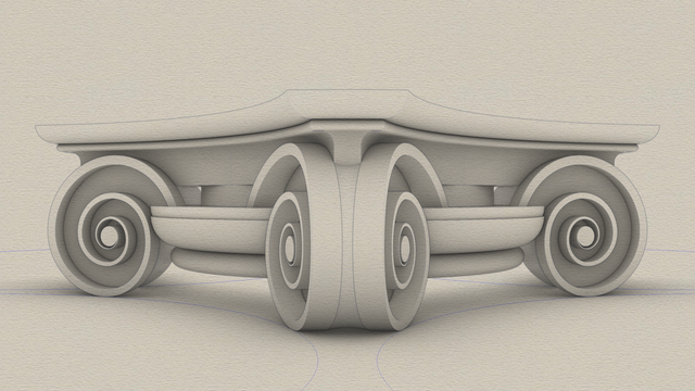
As mentioned in https://pixelfed.social/p/Splines/807933255910367093, we mentally rotate the floor plan of the modern #IonicCapital 45° so that the volute #spiral curves lie flat on the XZ plane.

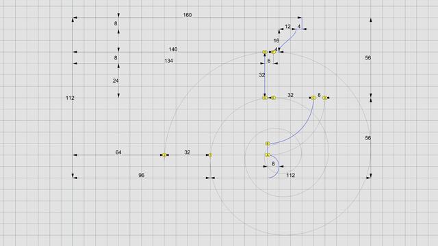
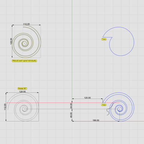
The top-left diagram shows the original volute spirals from https://pixelfed.social/p/Splines/800383518517869430. If you haven't already rebuilt them from disjointed arcs to seamless #NURBS curves as described in https://pixelfed.social/p/Splines/794199123072358090, do so now. Explode the whole spiral into constituent arcs, select all arcs for the outer spiral and join them separately, and repeat this step for the inner spiral. Then, rebuild both spirals with 256 segments each.

Volute spirals for the classic and modern variants are the exact same size, but the ones in the modern version appear smaller. That's an optical illusion because the spirals are rotated 90° in the modern version as shown in the bottom left diagram.

The bottom right diagram shows the placement of the volute spirals relative to the #profileCurves of the lower portion of the modern capital. The #voluteEye is slightly above and far to the right of the #astragal profile in the modern version compared to the classic version.

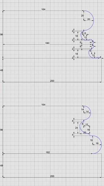
At this point, we make two copies of the volute spirals and trim them to the top of the #ovolo. In one copy we only trim away the outermost arms of the spirals while maintaining the inner spirals, as shown in the bottom right figure. In the other copy, we trim away the inner spirals as shown in the top right image.

The bottom right figure in https://babel.hathitrust.org/cgi/pt?id=mdp.39015031201190&view=1up&seq=142 shows the eye 6.5 parts (52 units) from column shaft. That's not an error, but poor documentation. See floor plan in https://pixelfed.social/p/Splines/807782440025967685 where x = 198 on the square is homologous to x = 250 on the circle. To reconcile, scale 52 by 250/198 = 65.656, or 66, and offset by 120 to get 186 units.
Splines (@[email protected])

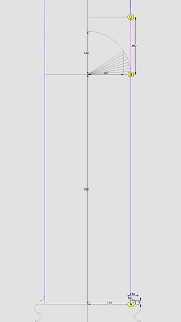
Left side of this diagram shows the #profileCurves for the cap of #ModernIonicCapital from the front. The right side shows a perspective view of the cap surfaces obtained by revolving the profile curves about their respective axes and after some of those have been trimmed away The measurements for the floor plan of the modern ionic capital are given in https://pixelfed.social/p/Splines/807782440025967685 with further links to relevant pages in #Scarlata's book at the bottom. I won't bore you with the bottom portion of the modern #capital because it is very similar to that of the classic capital shown in https://pixelfed.social/p/Splines/792124787573855518. A significant difference is that the bottom #ovolo is shorter, with a total height of 32 units instead of 40 For the cap, we need two identical copies of a single profile curve that is 30 units wide and 48 units tall. The curves marked by A and B in the diagram are oriented in the same direction and are spaced 100 units from each other. The bottom of profile curve A lines up with the neck of the #columnShaft at 120 units from the column axis. The revolution axis for this curve is located at 416 units from the column axis at the center of the largest circle in the floor plan. We #revolve profile curve A full circle about its revolution axis. Then, we #rotate the resulting surface about the column axis to get 4 identical copies. We revolve profile curve B full circle about the column axis. Then, we trim the resulting surface along with the 4 others at each intersection to get the side and corner surfaces for the cap of the capital. We #join the trimmed surfaces, cap #planarHoles to convert them into a closed solid, and verify that the resulting solid is #airtight with no #nakedEdges and no #nonManifoldEdges. The cap is in the correct final orientation. The volutes will be at 45° angles, but when we construct them, it will be easier to rotate the whole plan 45° so that the #volute #spiral is on the XZ plane.

Pixelfed
#ModernIonicCapital sketch

The modern #IonicCapital with curved faces and radial symmetry is a drop-in replacement for the classic Ionic capital with flat faces.

Unlike the classic variant, which has a rectangular footprint, the modern variant has a footprint that fits in a square. In the classic variant, the volutes and scrolls project out so that they are visible from the top. In the modern variant, there are no scrolls, the volutes have a curved face, and they are completely nestled under the top.

The sketch omits the #fillet at the bottom because we added that to the column #shaft in https://pixelfed.social/p/Splines/791794072490907090.

So, we start at the bottom with an #astragal which is exactly the same size as in the classic variant.

Next up from the bottom is the #ovolo which is shorter than in the classic variant. It still has a #tectonicSurface on which #decorativeElements rest, and a #virtualSurface that envelops the decorative elements. In this case, I chose a minimalist design with no #eggsAndDarts. Instead, I use another plain ovolo as a substitute that is offset from the tectonic surface by 1 part (or 8 units, when µ = 144).

Above the ovolo is the #channel, which in this case is a round slab whose surface matches the neck of the column with a radius equal to 5/6 of µ (120 units).

Above the channel is the #abacus which has a curved face that is repeated on all four sides. There is an abacus with flat sides in the classic variant as well, but it is not visible from the front because it is hidden behind the #volute slab. In fact, the vertical #braidsAssembly in the classic variant is attached to the abacus.

Above the abacus is a #reed, and above that, another small Ovolo that tops the modern capital.

The curved volutes follow the blue circular arcs at the bottom of the sketch. The volutes are shaped like a wedge, as can be seen more clearly in the corner facing the front. The portion of the wedge between the outer rims has a concave surface.
Splines (@[email protected])

The bottom 1/3 of the #columnShaft for an #IonicColumn is a perfect cylinder. So the line below point B is a straight line. In https://pixelfed.social/p/Splines/791723063470910081, we blended the bottom end of the 60° arc and the top end of the long interpolated curve between points J and K. Now blend the bottom end of the interpolated curve and the top end of the straight line between points B and C to obtain the 3rd and final #NURBS segment for the #primaryProfileCurve of the shaft. Just like there's a #cavetto and #fillet near the #neck of the shaft, there is a fillet and cavetto near the foot of the shaft. However, there is a subtle difference between the two. The cavetto near the neck is tangential to the blended #NURBS curve that is not a straight line. The profile curve for the cavetto near the foot is tangential to a straight line. There is a special name for a cavetto that is tangential to a straight line or flat surface, like the two cavetto moldings in the #dado of the #pedestal. It's called a #conge. Another alternate name for the cavetto molding is #cove, which is evocative of "cave" because of its concave profile curve. Above the neck is a fillet 8 units tall and an #astragal 16 units tall that #Scarlata puts in braces in the column shaft section within his tables of #VignolaProportions, with a note saying they are not counted as part of the shaft but are accounted for as part of the #capital. I decided to include the top fillet as part of the shaft and keep the astragal with the capital. It does not change the design or alter the proportions in any way, but the inclusion of the fillet makes it more practical for #3DPrinting and #CNCMilling of the neck. This concludes the profile curve for the shaft with a height of 291 parts or 2328 units + 8 for fillet. The column shaft is tapered in the upper 2/3 due to #entasis whose purpose is to make optical corrections to the shape of the column which, without correction, appeared concave near the top.

Pixelfed
Classic #IonicCapital #Tectonic Surfaces Plan

We already made the 8 unit tall #fillet at the bottom of the #capital a part of the #shaft in https://pixelfed.social/p/Splines/791794072490907090. So, excluding that, the remainder of the capital is 14 parts or 112 units tall, for the bottom half of which we use the #revolve operation (like the #columnBase and #columnShaft), and for the top half we use the #extrude operation (like the #pedestal, #entablature, and #plinth).

Starting at the bottom, we have an #astragal that is 2 parts or 16 units tall and has the same profile as a #reed and #torus, falling in between the two in terms of size. The arc AD is shown in gray because it is an invisible #virtualSurface that envelops the decorations like #eggsAndDarts on the #ovolo. This is the measurement that is given in #Scarlata's #PracticalArchitecture, but it makes no mention of the #decorative and #tectonic surfaces. Arc BC with a radius of 4 parts or 32 units is the tectonic surface on which the Ovolo decorations rest. Such decorations have a variable or uneven surface which may not exceed 1 part or 8 units.

Points E and F mark the horizontal tangent or maxima of the second spiral and the first (outermost) spiral, respectively. The gap between them is exactly 4 parts or 32 units. GH is the profile for the vertical side surface on which part of the #ribbon and #braid lie flat, protruding exactly 6 units to coincide with the invisible virtual flat surface through EF.

The #cymaReversa is 2 parts or 16 units tall and 1.5 parts or 12 units wide. It starts 4 units to the right of F and stops 4 units short of the top fillet, which is one part or 8 units tall and 20 parts or 160 units from the #columnAxis.

Of the 4 parts or 32 units between G and H, the lower 3 parts or 24 units are part of the #voluteChannel groove and the top 1 part or 8 units is a fillet that follows the curve of the #volute and progressively gets narrower until it converges with the #eye of the volute.
Splines (@[email protected])

The bottom 1/3 of the #columnShaft for an #IonicColumn is a perfect cylinder. So the line below point B is a straight line. In https://pixelfed.social/p/Splines/791723063470910081, we blended the bottom end of the 60° arc and the top end of the long interpolated curve between points J and K. Now blend the bottom end of the interpolated curve and the top end of the straight line between points B and C to obtain the 3rd and final #NURBS segment for the #primaryProfileCurve of the shaft. Just like there's a #cavetto and #fillet near the #neck of the shaft, there is a fillet and cavetto near the foot of the shaft. However, there is a subtle difference between the two. The cavetto near the neck is tangential to the blended #NURBS curve that is not a straight line. The profile curve for the cavetto near the foot is tangential to a straight line. There is a special name for a cavetto that is tangential to a straight line or flat surface, like the two cavetto moldings in the #dado of the #pedestal. It's called a #conge. Another alternate name for the cavetto molding is #cove, which is evocative of "cave" because of its concave profile curve. Above the neck is a fillet 8 units tall and an #astragal 16 units tall that #Scarlata puts in braces in the column shaft section within his tables of #VignolaProportions, with a note saying they are not counted as part of the shaft but are accounted for as part of the #capital. I decided to include the top fillet as part of the shaft and keep the astragal with the capital. It does not change the design or alter the proportions in any way, but the inclusion of the fillet makes it more practical for #3DPrinting and #CNCMilling of the neck. This concludes the profile curve for the shaft with a height of 291 parts or 2328 units + 8 for fillet. The column shaft is tapered in the upper 2/3 due to #entasis whose purpose is to make optical corrections to the shape of the column which, without correction, appeared concave near the top.

Pixelfed
The bottom 1/3 of the #columnShaft for an #IonicColumn is a perfect cylinder. So the line below point B is a straight line.

In https://pixelfed.social/p/Splines/791723063470910081, we blended the bottom end of the 60° arc and the top end of the long interpolated curve between points J and K. Now blend the bottom end of the interpolated curve and the top end of the straight line between points B and C to obtain the 3rd and final #NURBS segment for the #primaryProfileCurve of the shaft.

Just like there's a #cavetto and #fillet near the #neck of the shaft, there is a fillet and cavetto near the foot of the shaft. However, there is a subtle difference between the two. The cavetto near the neck is tangential to the blended #NURBS curve that is not a straight line. The profile curve for the cavetto near the foot is tangential to a straight line.

There is a special name for a cavetto that is tangential to a straight line or flat surface, like the two cavetto moldings in the #dado of the #pedestal. It's called a #conge. Another alternate name for the cavetto molding is #cove, which is evocative of "cave" because of its concave profile curve.

Above the neck is a fillet 8 units tall and an #astragal 16 units tall that #Scarlata puts in braces in the column shaft section within his tables of #VignolaProportions, with a note saying they are not counted as part of the shaft but are accounted for as part of the #capital.

I decided to include the top fillet as part of the shaft and keep the astragal with the capital. It does not change the design or alter the proportions in any way, but the inclusion of the fillet makes it more practical for #3DPrinting and #CNCMilling of the neck. This concludes the profile curve for the shaft with a height of 291 parts or 2328 units + 8 for fillet.

The column shaft is tapered in the upper 2/3 due to #entasis whose purpose is to make optical corrections to the shape of the column which, without correction, appeared concave near the top.
Splines (@[email protected])

The section between points J and K is the #neck of the #shaft. The blue #primaryProfileCurve below J is the #interpolated #NURBS curve we fit through 8 points in https://pixelfed.social/p/Splines/791526497210906825. The neck is conceptually divided into three bands, each 1 part (8 units) tall. In the top 2/3, we draw a circular 90° arc with radius of 16 units, divide it into thirds, and discard the lower 30° portion. Then, blend the lower end of the arc and upper end of the interpolated NURBS curve to create a new NURBS curve shown here in magenta. Zoom in, and you will see that it deviates slightly from the original 90° arc. This is because the blended curve is tangential to the 60° arc and the longer NURBS curve. When joined, the three sections form a smooth continuously differentiable NURBS curve. This level of precision is only needed for engineering work. If you just want a #charcoal #sketch, #draw in #ink, #paint in #watercolor, or even make #clay or #ceramic #basrelief, then you don't even need a #CAD program. A compass and protractor are sufficient. Just blend the shapes by hand as closely as you can. The imperfections, if any will be imperceptible. This brings us back to the previous post. If you're not using CAD, how do you obtain the 8 points C through J using manual tools? Look closely at the radiating lines, first of which passes through point B and the last one reaches point 8. An easy way to find the angle between these two lines is to use basic trigonometry. Focus on the center of the arc, follow up to point 8, and then drop down vertically where the horizontal line is split at 120 units, and close back to the origin. This is a right triangle whose hypotenuse is the radius of the arc. The cosine of the angle between the base and the hypotenuse is 120/144 = 0.83333333. So the angle itself is arc cosine of 0.83333333, or 33.55730976°. For hand drawing, round it off to 33.6°. Then divide that into 8 parts of 4.2° each to plot points 1 through 8.

Pixelfed
#IonicColumn #VignolaBase and #AtticBase #CAD Plans

Both #Vignola base and #Attic base have the same square footprint of 400 units x 400 units. The #plinth for both is 48 units (6 parts, or µ/3) tall, and the total height for both is 144 units (18 parts, or exactly µ). As such, they are easily interchangeable.

In the Vignola variant, we start at the plinth with a #fillet 2 units tall and a classic #scotia 18 units tall gouging out part of the fillet.

Then there is another fillet 2 units tall, followed by two #reeds, each 8 units tall, followed by another classic scotia as described above.

This is followed by yet another fillet 2 units tall and topped off with a #torus 40 units tall. A Torus is the same as a reed, except larger. When we reach the neck of the shaft, we will see another molding called #Astragal which has the same profile as reed and torus, but sits in the middle in size. Think of reed, astragal, and torus as small, medium, and large of the same profile.

The modern Attic variant is more elegant with fewer moldings. It also gives the impression of more heft for more stately columns. It starts at the plinth with a torus 36 units tall, followed by a fillet 4 units tall, followed by a modern scotia 24 units tall, followed by another fillet 4 units tall, and topped off with another torus 28 units tall.

As in the construction of #IonicEntablature [https://pixelfed.social/p/Splines/791013152244518907], split the construction of the #columnBase into two steps.

Just as we extruded #dentils separately, we extrude the plinth separately. First draw a square 400x400 in the top view. Then extrude the square 48 units in the front view.

For the rest of the base, we need a new 3D operation — #revolve around an axis. Instead of extruding the #primaryProfileCurve, we revolve it around the #columnAxis, and cap the #planarHoles on both ends before performing a #booleanUnion with the plinth. Finally check edges of the solid for #nakedEdges and #nonManifoldEdges.
Splines (@[email protected])

This sketch shows the arrangement of #dentils in the classic variation of the #IonicEntablature. It shows the full layout, but most of the top is obscured by the top portion of the #cornice. Only the outside square shapes are actually visible. Each #dentil has a square "footprint" that is 4 parts by 4 parts (32*32 units) and is 6 parts (48 units) tall. The spacing between each dentil is 2 parts (16 units). Dentils project 4 parts (or 32 units) from the face of the #fascia on which they rest. Each face of the fascia has 7 dentils with the middle dentil laterally centered and directly in front of the column axis. The 2 side dentils are on side faces, and that is apparent in the darker shading in the sketch at https://pixelfed.social/i/web/post/790782316675150160. Take the time to reconcile this with the numbers listed in #Scarlata's #PracticalArchitecture. The 3D reconstruction from the #primaryProfileCurves is very similar to that of the #IonicPedestal, with #extrusion, #mitering, #joining, and #capping planar holes as described in https://pixelfed.social/i/web/post/790645054230337543 — just set the dentils aside, for now. Once you have capped the #planarHoles to get a solid, analyze the edges of the solid in the #CAD program for #nakedEdges and #nonManifoldEdges. Then, extrude the dentils outline (in the top view) to a height of 48 units (in the front view). Now perform a #booleanUnion of the two solid shapes to get the complete #entablature. Finally, check the edges of the solid in the #CAD program AGAIN for #nakedEdges and #nonManifoldEdges. With this, we have finished two of the three main components of the #IonicOrder. There's a modern version of the Ionic entablature with #modillions, which I will describe later. Next, we move on to the biggest, most conspicuous part of the order — the #IonicColumn.

Pixelfed
Word Search Puzzle 331

Word List : #india #saggered #astragal #surcoats #overnear #dopper #sation #chieve #hedgier #dropshot #monose #skaldic #frieda #pashes #saltweed #subclass #venery #godheads

Kara Finance