#IonicColumn

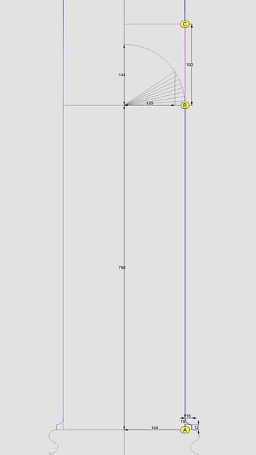
#Flutes have a different configuration in the #IonicOrder than they do in the #DoricOrder. In #Doric, the flutes run right next to each other, dividing the circumference of the column into 24 equal sectors, or 15° each.

In #Ionic, there is a small gap between the flutes. This gap used to vary, but over time, Ionic designers seemed to have settled and standardized the measurements by splitting 15° in 4:1 ratio, giving 12° to a flute and 3° to the gap between flutes.

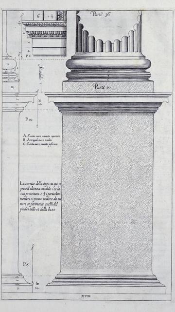
Because of this standardization, there would seem to be little room for variants, but there is. In his #RegolaArchitettura [see https://archive.org/details/gri_33125008229458/page/n37/mode/2up], #Vignola documented flutes with hemispherical tops but flat bottoms, as shown in the image here.

However, it is acceptable to have hemispheres at both top and bottom as long as they are consistently used within a #colonnade or #arcade.

Flute geometry is interesting. Just like the #IonicColumn #shaft, a flute also gradually tapers as it rises from bottom to top. Additionally, it bends along the shaft surface due to #entasis [see https://pixelfed.social/p/Splines/791794072490907090]. In other words, flutes hug the column shaft.

Unlike other decorative elements like #eggsAndDarts and #3StrandBraids, flutes are #subtractive, not #additive to the rest of the design. In other words, we have to carve the flutes out instead of adding them to the design.
Regola delli cinque ordini d' architettura : Vignola, 1507-1573 : Free Download, Borrow, and Streaming : Internet Archive

48 leaves : 44 cm (fol.)

Internet Archive
The bottom 1/3 of the #columnShaft for an #IonicColumn is a perfect cylinder. So the line below point B is a straight line.

In https://pixelfed.social/p/Splines/791723063470910081, we blended the bottom end of the 60° arc and the top end of the long interpolated curve between points J and K. Now blend the bottom end of the interpolated curve and the top end of the straight line between points B and C to obtain the 3rd and final #NURBS segment for the #primaryProfileCurve of the shaft.

Just like there's a #cavetto and #fillet near the #neck of the shaft, there is a fillet and cavetto near the foot of the shaft. However, there is a subtle difference between the two. The cavetto near the neck is tangential to the blended #NURBS curve that is not a straight line. The profile curve for the cavetto near the foot is tangential to a straight line.

There is a special name for a cavetto that is tangential to a straight line or flat surface, like the two cavetto moldings in the #dado of the #pedestal. It's called a #conge. Another alternate name for the cavetto molding is #cove, which is evocative of "cave" because of its concave profile curve.

Above the neck is a fillet 8 units tall and an #astragal 16 units tall that #Scarlata puts in braces in the column shaft section within his tables of #VignolaProportions, with a note saying they are not counted as part of the shaft but are accounted for as part of the #capital.

I decided to include the top fillet as part of the shaft and keep the astragal with the capital. It does not change the design or alter the proportions in any way, but the inclusion of the fillet makes it more practical for #3DPrinting and #CNCMilling of the neck. This concludes the profile curve for the shaft with a height of 291 parts or 2328 units + 8 for fillet.

The column shaft is tapered in the upper 2/3 due to #entasis whose purpose is to make optical corrections to the shape of the column which, without correction, appeared concave near the top.
Splines (@[email protected])

The section between points J and K is the #neck of the #shaft. The blue #primaryProfileCurve below J is the #interpolated #NURBS curve we fit through 8 points in https://pixelfed.social/p/Splines/791526497210906825. The neck is conceptually divided into three bands, each 1 part (8 units) tall. In the top 2/3, we draw a circular 90° arc with radius of 16 units, divide it into thirds, and discard the lower 30° portion. Then, blend the lower end of the arc and upper end of the interpolated NURBS curve to create a new NURBS curve shown here in magenta. Zoom in, and you will see that it deviates slightly from the original 90° arc. This is because the blended curve is tangential to the 60° arc and the longer NURBS curve. When joined, the three sections form a smooth continuously differentiable NURBS curve. This level of precision is only needed for engineering work. If you just want a #charcoal #sketch, #draw in #ink, #paint in #watercolor, or even make #clay or #ceramic #basrelief, then you don't even need a #CAD program. A compass and protractor are sufficient. Just blend the shapes by hand as closely as you can. The imperfections, if any will be imperceptible. This brings us back to the previous post. If you're not using CAD, how do you obtain the 8 points C through J using manual tools? Look closely at the radiating lines, first of which passes through point B and the last one reaches point 8. An easy way to find the angle between these two lines is to use basic trigonometry. Focus on the center of the arc, follow up to point 8, and then drop down vertically where the horizontal line is split at 120 units, and close back to the origin. This is a right triangle whose hypotenuse is the radius of the arc. The cosine of the angle between the base and the hypotenuse is 120/144 = 0.83333333. So the angle itself is arc cosine of 0.83333333, or 33.55730976°. For hand drawing, round it off to 33.6°. Then divide that into 8 parts of 4.2° each to plot points 1 through 8.

Pixelfed
Slowly but surely getting the hang of these letters
#Entasis #BlackLetter
1st day's #blackletter practice. Bleeding paper! #Entasis