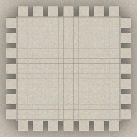
Each #dentil has a square "footprint" that is 4 parts by 4 parts (32*32 units) and is 6 parts (48 units) tall. The spacing between each dentil is 2 parts (16 units).
Dentils project 4 parts (or 32 units) from the face of the #fascia on which they rest.
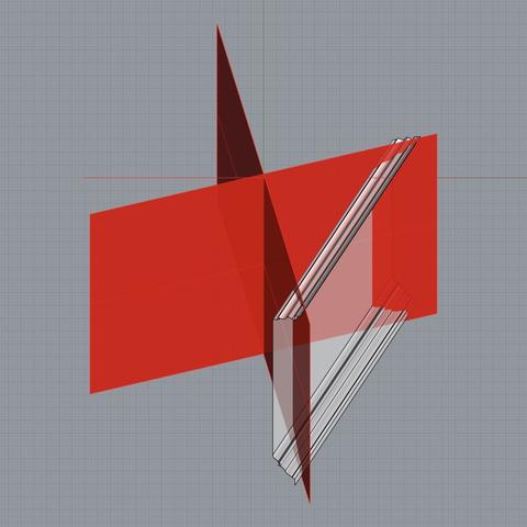
Each face of the fascia has 7 dentils with the middle dentil laterally centered and directly in front of the column axis. The 2 side dentils are on side faces, and that is apparent in the darker shading in the sketch at https://pixelfed.social/i/web/post/790782316675150160. Take the time to reconcile this with the numbers listed in #Scarlata's #PracticalArchitecture.
The 3D reconstruction from the #primaryProfileCurves is very similar to that of the #IonicPedestal, with #extrusion, #mitering, #joining, and #capping planar holes as described in https://pixelfed.social/i/web/post/790645054230337543 — just set the dentils aside, for now.
Once you have capped the #planarHoles to get a solid, analyze the edges of the solid in the #CAD program for #nakedEdges and #nonManifoldEdges.
Then, extrude the dentils outline (in the top view) to a height of 48 units (in the front view).
Now perform a #booleanUnion of the two solid shapes to get the complete #entablature.
Finally, check the edges of the solid in the #CAD program AGAIN for #nakedEdges and #nonManifoldEdges.
With this, we have finished two of the three main components of the #IonicOrder. There's a modern version of the Ionic entablature with #modillions, which I will describe later.
Next, we move on to the biggest, most conspicuous part of the order — the #IonicColumn.

Splines (@[email protected])
There are two variations of the #IonicEntablature. The classic variation has #dentils, which are teeth-like structures shown here above the #frieze. The modern version has #modillions, which are projecting brackets under the #corona of the #cornice. Well, "modern" is a relative term. For designs that are more than 2000 years old, even an alteration 1000 years ago would qualify as modern. Although the sketch shows the #entablature with a square footprint, in practice, it runs the entire length of a #colonnade (multiple columns) or an #arcade (multiple arches). #CAD construction of the entablature is very similar to that of a #pedestal. The first step is to consult #Vignola's #RegolaArchitettura for the visual appearance, and then consult #Scarlata's #PracticalArchitecture for #VignolaProportions in tabular form. It is convenient to create a spreadsheet to convert the measurements given in Scarlata's book from module "parts" to your own model units based on your choice of value for the module parameter µ. Armed with these measurements, it is time to plot the points and draw the #primaryProfileCurves on our standard 2D grid with minor grid lines 8 units apart and major grid lines 32 units apart. In the first pass, skip the dentils and draw the profile curves for the rest of the moldings. Just as with the pedestal, I will show the macro-level plan as well as the detail plan. So, you don't have to go to Scarlata's book, but you know it's there if you want to. I will show the dentil arrangement in a subsequent post. Based on µ = 144, the classic Ionic entablature is 648 units (36 parts, or 4.5*µ) tall. Of this, the #architrave at the bottom is 180 units (10 parts, or 1.25*µ) tall, the frieze in the middle is 216 units (12 parts, or 1.5*µ) tall, and the cornice at the top is 252 units (14 parts, or 1.75*µ) tall.