#ReverseEngineer #ImageScans

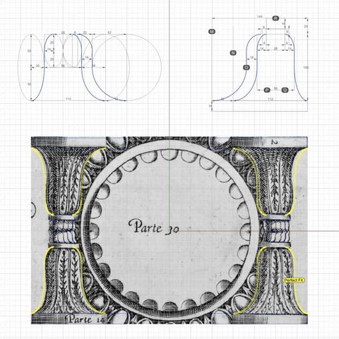
We now dig into the archives and resurface old sketches for #restoration. This one is from #Vignola's #RegolaArchitettura at https://archive.org/details/gri_33125008229458/page/n39/mode/2up. This lavishly illustrated book with copious notes that also flaunt his #calligraphy was written (in Italian) when America was still a British colony. The book went out of copyright a long time ago.

Straighten the image as much as you can in an image editor and crop it before bringing it into a #CAD tool.

Then, stare at the image for a while and squint occasionally until you "see" crucial features and patterns emerge, while ignoring the "noise."

Finally, try #curveFitting with the simplest of curves — straight lines, circular arcs, ellipse, and so on to get as close an approximation as possible. Remember that with hand-drawn sketches, the fit will rarely be perfect. So use some structure as a guide or #scaffolding as I laid out in https://pixelfed.social/p/Splines/792966507797633558.

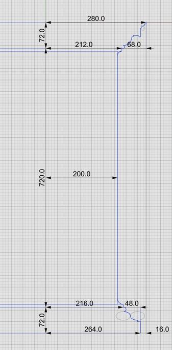
In the top left of the diagram, I show the measurements that I was satisfied with after a lengthy process of trial and error because the numbers comport with my understanding of the proportions the original designers intended — many, but not all of which are documented in #Scarlata's #PracticalArchitecture with #VignolaProportions in tabular form.

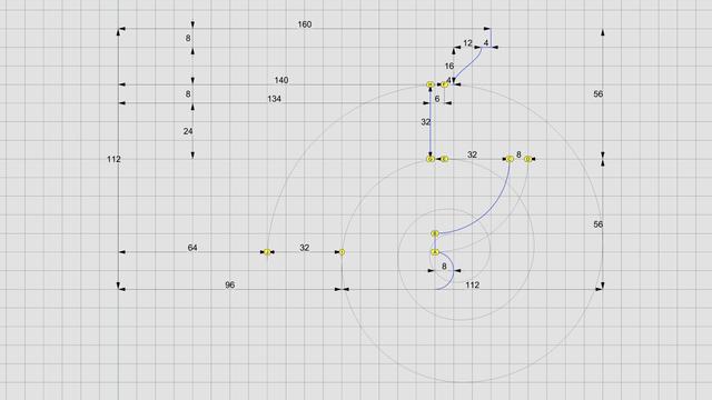
For measurements that are missing, use plausible heuristics to fill in the blanks and try to justify your choices using simple rules. In this case, the bedrock rules are:

1. The entire #volute is exactly µ = 144 units wide, including #ArcZero, which extends 32 units beyond the portion of the volute that is actually used in the design.

2. The portion of the volute that is actually used in the design is 112 units wide, same as the height of the unadorned #capital.

3. Width of the #scroll bell shape as seen from the bottom is 112 units in front, 56 units in the middle and 28 units in the rear — all in #geometricSequence.
Regola delli cinque ordini d' architettura : Vignola, 1507-1573 : Free Download, Borrow, and Streaming : Internet Archive

48 leaves : 44 cm (fol.)

Internet Archive
Classic #IonicCapital #Tectonic Surfaces Plan

We already made the 8 unit tall #fillet at the bottom of the #capital a part of the #shaft in https://pixelfed.social/p/Splines/791794072490907090. So, excluding that, the remainder of the capital is 14 parts or 112 units tall, for the bottom half of which we use the #revolve operation (like the #columnBase and #columnShaft), and for the top half we use the #extrude operation (like the #pedestal, #entablature, and #plinth).

Starting at the bottom, we have an #astragal that is 2 parts or 16 units tall and has the same profile as a #reed and #torus, falling in between the two in terms of size. The arc AD is shown in gray because it is an invisible #virtualSurface that envelops the decorations like #eggsAndDarts on the #ovolo. This is the measurement that is given in #Scarlata's #PracticalArchitecture, but it makes no mention of the #decorative and #tectonic surfaces. Arc BC with a radius of 4 parts or 32 units is the tectonic surface on which the Ovolo decorations rest. Such decorations have a variable or uneven surface which may not exceed 1 part or 8 units.

Points E and F mark the horizontal tangent or maxima of the second spiral and the first (outermost) spiral, respectively. The gap between them is exactly 4 parts or 32 units. GH is the profile for the vertical side surface on which part of the #ribbon and #braid lie flat, protruding exactly 6 units to coincide with the invisible virtual flat surface through EF.

The #cymaReversa is 2 parts or 16 units tall and 1.5 parts or 12 units wide. It starts 4 units to the right of F and stops 4 units short of the top fillet, which is one part or 8 units tall and 20 parts or 160 units from the #columnAxis.

Of the 4 parts or 32 units between G and H, the lower 3 parts or 24 units are part of the #voluteChannel groove and the top 1 part or 8 units is a fillet that follows the curve of the #volute and progressively gets narrower until it converges with the #eye of the volute.
Splines (@Splines@pixelfed.social)

The bottom 1/3 of the #columnShaft for an #IonicColumn is a perfect cylinder. So the line below point B is a straight line. In https://pixelfed.social/p/Splines/791723063470910081, we blended the bottom end of the 60° arc and the top end of the long interpolated curve between points J and K. Now blend the bottom end of the interpolated curve and the top end of the straight line between points B and C to obtain the 3rd and final #NURBS segment for the #primaryProfileCurve of the shaft. Just like there's a #cavetto and #fillet near the #neck of the shaft, there is a fillet and cavetto near the foot of the shaft. However, there is a subtle difference between the two. The cavetto near the neck is tangential to the blended #NURBS curve that is not a straight line. The profile curve for the cavetto near the foot is tangential to a straight line. There is a special name for a cavetto that is tangential to a straight line or flat surface, like the two cavetto moldings in the #dado of the #pedestal. It's called a #conge. Another alternate name for the cavetto molding is #cove, which is evocative of "cave" because of its concave profile curve. Above the neck is a fillet 8 units tall and an #astragal 16 units tall that #Scarlata puts in braces in the column shaft section within his tables of #VignolaProportions, with a note saying they are not counted as part of the shaft but are accounted for as part of the #capital. I decided to include the top fillet as part of the shaft and keep the astragal with the capital. It does not change the design or alter the proportions in any way, but the inclusion of the fillet makes it more practical for #3DPrinting and #CNCMilling of the neck. This concludes the profile curve for the shaft with a height of 291 parts or 2328 units + 8 for fillet. The column shaft is tapered in the upper 2/3 due to #entasis whose purpose is to make optical corrections to the shape of the column which, without correction, appeared concave near the top.

Pixelfed
This sketch shows the arrangement of #dentils in the classic variation of the #IonicEntablature. It shows the full layout, but most of the top is obscured by the top portion of the #cornice. Only the outside square shapes are actually visible.

Each #dentil has a square "footprint" that is 4 parts by 4 parts (32*32 units) and is 6 parts (48 units) tall. The spacing between each dentil is 2 parts (16 units).

Dentils project 4 parts (or 32 units) from the face of the #fascia on which they rest.

Each face of the fascia has 7 dentils with the middle dentil laterally centered and directly in front of the column axis. The 2 side dentils are on side faces, and that is apparent in the darker shading in the sketch at https://pixelfed.social/i/web/post/790782316675150160. Take the time to reconcile this with the numbers listed in #Scarlata's #PracticalArchitecture.

The 3D reconstruction from the #primaryProfileCurves is very similar to that of the #IonicPedestal, with #extrusion, #mitering, #joining, and #capping planar holes as described in https://pixelfed.social/i/web/post/790645054230337543 — just set the dentils aside, for now.

Once you have capped the #planarHoles to get a solid, analyze the edges of the solid in the #CAD program for #nakedEdges and #nonManifoldEdges.

Then, extrude the dentils outline (in the top view) to a height of 48 units (in the front view).

Now perform a #booleanUnion of the two solid shapes to get the complete #entablature.

Finally, check the edges of the solid in the #CAD program AGAIN for #nakedEdges and #nonManifoldEdges.

With this, we have finished two of the three main components of the #IonicOrder. There's a modern version of the Ionic entablature with #modillions, which I will describe later.

Next, we move on to the biggest, most conspicuous part of the order — the #IonicColumn.
Splines (@Splines@pixelfed.social)

There are two variations of the #IonicEntablature. The classic variation has #dentils, which are teeth-like structures shown here above the #frieze. The modern version has #modillions, which are projecting brackets under the #corona of the #cornice. Well, "modern" is a relative term. For designs that are more than 2000 years old, even an alteration 1000 years ago would qualify as modern. Although the sketch shows the #entablature with a square footprint, in practice, it runs the entire length of a #colonnade (multiple columns) or an #arcade (multiple arches). #CAD construction of the entablature is very similar to that of a #pedestal. The first step is to consult #Vignola's #RegolaArchitettura for the visual appearance, and then consult #Scarlata's #PracticalArchitecture for #VignolaProportions in tabular form. It is convenient to create a spreadsheet to convert the measurements given in Scarlata's book from module "parts" to your own model units based on your choice of value for the module parameter µ. Armed with these measurements, it is time to plot the points and draw the #primaryProfileCurves on our standard 2D grid with minor grid lines 8 units apart and major grid lines 32 units apart. In the first pass, skip the dentils and draw the profile curves for the rest of the moldings. Just as with the pedestal, I will show the macro-level plan as well as the detail plan. So, you don't have to go to Scarlata's book, but you know it's there if you want to. I will show the dentil arrangement in a subsequent post. Based on µ = 144, the classic Ionic entablature is 648 units (36 parts, or 4.5*µ) tall. Of this, the #architrave at the bottom is 180 units (10 parts, or 1.25*µ) tall, the frieze in the middle is 216 units (12 parts, or 1.5*µ) tall, and the cornice at the top is 252 units (14 parts, or 1.75*µ) tall.

Pixelfed
There are two variations of the #IonicEntablature. The classic variation has #dentils, which are teeth-like structures shown here above the #frieze. The modern version has #modillions, which are projecting brackets under the #corona of the #cornice. Well, "modern" is a relative term. For designs that are more than 2000 years old, even an alteration 1000 years ago would qualify as modern.

Although the sketch shows the #entablature with a square footprint, in practice, it runs the entire length of a #colonnade (multiple columns) or an #arcade (multiple arches).

#CAD construction of the entablature is very similar to that of a #pedestal.

The first step is to consult #Vignola's #RegolaArchitettura for the visual appearance, and then consult #Scarlata's #PracticalArchitecture for #VignolaProportions in tabular form.

It is convenient to create a spreadsheet to convert the measurements given in Scarlata's book from module "parts" to your own model units based on your choice of value for the module parameter µ.

Armed with these measurements, it is time to plot the points and draw the #primaryProfileCurves on our standard 2D grid with minor grid lines 8 units apart and major grid lines 32 units apart.

In the first pass, skip the dentils and draw the profile curves for the rest of the moldings. Just as with the pedestal, I will show the macro-level plan as well as the detail plan. So, you don't have to go to Scarlata's book, but you know it's there if you want to.

I will show the dentil arrangement in a subsequent post.

Based on µ = 144, the classic Ionic entablature is 648 units (36 parts, or 4.5*µ) tall. Of this, the #architrave at the bottom is 180 units (10 parts, or 1.25*µ) tall, the frieze in the middle is 216 units (12 parts, or 1.5*µ) tall, and the cornice at the top is 252 units (14 parts, or 1.75*µ) tall.
This shows macro-level measurements for the #IonicPedestal.

The key to #effectiveModeling is to simplify a complex shape into elementary components. Sometimes, this involves mentally flattening and reducing 3D shapes to 2D shapes, extracting elementary curves from them, and then recreating the 3D shapes from the extracted 2D curves.

This is not always easy for organic shapes (which can still be approximated by Bézier curves). I extracted the #primaryCurves for the #IonicScroll surface in https://pixelfed.social/p/Splines/789956327130679640 after a lengthy trial-and-error process that involved #curveFitting images from #Vignola’s book, #RegolaArchitettura. I had to #reverseEngineer the details because the measurements have either been lost, or are locked away in some library. Web search yields no details on these measurements.

Fortunately, for geometrical shapes like pedestals, this is very easy. Because of its square footprint, mentally slicing it through the middle from top to bottom, it is easy to “see” the outline. Another way to think about #curveExtraction is to shine an imaginary bright light on an object from behind in a dark room to reveal its silhouette.

For the pedestal, even this silhouette or outline can be further reduced because the shape is symmetrical about the #columnAxis. With this realization, we only need to focus on one half of the outline, and methodically proceed from bottom to top, marking every kink and inflection point on the outline.

Fortunately, the other authoritative book, #Scarlata’s #PracticalArchitecture, I mentioned in my introductory post already documents #VignolaProportions in tabular form. So we can skip everything else and go directly to that.

Total height of #IonicPedestal is 864 units (108 parts, or 6*µ) of which the #PedestalBasement and #PedestalCap are each 72 units (9 parts, or µ/2) and the #Dado is 720 units (90 parts, or µ*5) tall.
Splines (@Splines@pixelfed.social)

This sweeping shape is a timeless design that first appeared in the scrolls of the #IonicCapital as the most distinctive part of the #IonicOrder in classical Greco-Roman architecture more than 2500 years ago. Shown here with a zebra pattern on the wireframe of a CAD model to accentuate its features and attest to the smoothness of its 3-dimensional surface, the design has been refined many times since the original version over the last two millennia. The two most remarkable things about this design are that: — It can be recreated with modern CAD tools by drawing simple 2-dimensional straight lines and circular arcs exclusively. The end result is truly breathtaking and makes one wonder how architects visualized the result and put theory into practice. In the CAD model, the ultimate surface is a #NURBS surface that uses #BSplines extensively, but none of the B-splines or surfaces need to be created "by hand." One only has to draw straight lines and circular arcs with accurate measurements snapped to grids. — For a design that has survived the ages, it is lamentable how few authoritative sources that accurately describe fine details and exact reconstruction methodology remain accessible to the general public in the age of Internet. The most comprehensive is the 10-volume tome that Marcus #Vitruvius Pollio, a Roman architect and engineer, wrote for #JuliusCaesar and his successor Emperor #CaesarAugustus. [https://www.gutenberg.org/files/20239/20239-h/20239-h.htm] I frequently use two more authoritative sources: — "Regola delli cinque ordini d' architettura," or simply #RegolaArchitettura by Giacomo Barozzi da #Vignola [https://archive.org/details/gri_33125008229458/page/n3/mode/2up], and — "A Course in Theoretical and Practical Architecture," or simply #PracticalArchitecture by Francisco Salvatore #Scarlata (#Bordonaro), which documents #VignolaProportions in tabular form [https://babel.hathitrust.org/cgi/pt?id=mdp.39015031201190&view=1up&seq=5]

Pixelfed