#Arcade #Intercolumniation without #Pedestal

In https://pixelfed.social/p/Splines/803089629244302486, we saw #simpleIntercolumniation, also known as #Architravato.

Roman architects combined columns with walls thick enough to bury half of the column width inside the walls and added arches to them for better load distribution. An arcade (multiple arches) can be run in series along a single wall, or in parallel to form a walkway. They can also be combined in both series and parallel configurations, perhaps the most famous of which is the #Colosseum in Rome.

In the Colosseum, the outer walls follow an elliptical curve (even though it looks circular from the outside), and it has multiple tiers of arches in series. The interior has arches in concentric passageways in the lower tiers giving it a lattice-like design.

Because arches distribute the load from above, they allow for wider intercolumniation. The rules for #ArcadeIntercolumniation differ depending on whether the columns have pedestals or not.

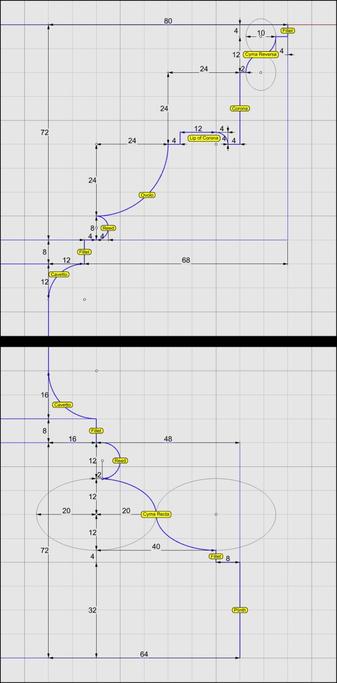
Besides the arch itself, which is part of the wall, the figure shows some new architectural elements.

The narrow part of the wall immediately behind a column is known as a #pier. The visible face of a pier between a column and the opening under the arch is known as #alette. The base of the pier has a molding, the flat part of which has the same height as the column base (µ) while the rest follows the #fillet and #cavetto or #conge of the #shaft.

As we move up the pier, there is a horizontal molding known as #impost just below where the arc of the arch starts. The impost wraps around on the sides of the pier.

Around the arc is a circular molding known as #archivolt, the bottom portion of which has a #fascia that is aligned with the face of the wall.

The wall itself extends all the way to the top of the #entablature. It is worth noting that the entablature is repeated on the wall. It doesn't end at the columns and has two "outside" corners and one "inside" corner.
Splines (@[email protected])

Side View of a #Peripteral (#Sexastyle) #Colonnade with #IonicColumns arranged in #Eustyle #intercolumniation. In my previous post at https://pixelfed.social/p/Splines/803076419096100108, I mentioned that the consensus sweet spot for inter-column spacing was 2.25 diameters (4.5µ) between column shafts at the bottom (6.5µ axis-to-axis), except for the two middle columns where the spacing was 3 column diameters (8µ from axis-to-axis). This variable intercolumniation is only for #colonnades in the front and back. The spacing between columns on the sides is uniform as shown in the image here. Something worth noting in this image is the number of columns on each side. In a peripteral (sexastyle) building, there are 6 columns in the front (and back) with 5 intercolumniations between them. On the sides, it is an error to double the number of columns on the sides. Instead, the number of intercolumniations is doubled — in this case from 5 to 10, giving us 11 columns. So, the number of columns is always even in the front, and always odd on the sides (one less than twice the number of columns in the front). On the topic of even and odd, also note that the number of steps leading up to the base of the colonnade is always odd. #Vitruvious suggested keeping the rise between 9" - 12" and the run twice that, or between 18" - 24". Note that these measurements are in physical units — a marked departure from the abstract µ = 144 units we have been using all along. The rules for intercolumniation presented so far are known as #simpleIntercolumniation. When the Romans introduced #arches and combined them with #halfColumns to produce #arcades, the rules were adapted for the new design. Because the arches distributed the load from the beams above, it allowed for wider intercolumniation. With the addition of #pedestals, the gap was made even wider still, and the look of the complete edifice is just majestic! With half-columns and arches, we will see some new architectural elements.

Pixelfed
#IonicColumn #Flutes

This diagram shows the 2D geometry of an #Ionic #flute. The larger blue circle shows the flute outline near the #base of the #column. The smaller blue circle shows the flute outline near the #neck of the #shaft. Both subtend a 12° angle at the center of the column.

Like an egg in the #EggsAndDarts motif, a flute must be centered on the column axis when viewed directly from the front, back, or the sides. This is why the 12° are split into 6° on either side of the X axis. The center of the larger circle is µ = 144 units from the origin on the X axis. The center of the smaller circle is 5/6 of µ, or 120 units from the origin.

In https://pixelfed.social/p/Splines/799340150182400358, I mentioned working at sub-micron precision, and you might wonder where that came from when we have been using abstract units like µ without specifying any physical units. My apologies for not making it clear that I had assumed 1 unit was equal to 1 mm. If that assumption holds, then µ = 144 mm gives a total order height of 4104 mm, that is 13.46 ft. At smaller scales, the precision is even higher than 1/10 of a micron.

With that said, here the radius of the larger circle is 15.0728 units and that of the smaller circle is 12.5606 units, with sub-micron precision if 1 unit = 1 mm.

Refer to https://pixelfed.social/p/Splines/791399680747885646 and place the center of the smaller circle exactly at point J on the neck line. Later we will draw a sphere at the same location with the same radius.

If you want a flat bottom for flutes, place the center of the larger circle at exactly 28 units (12 for the #fillet and 16 for the #cavetto or #conge) above point A in that figure. If you want a round bottom, then further move the larger circle up by the size of its radius.

Nobody would quibble if you used a radius of 15 units instead of 15.0728 units, but it would make it easier to switch from flat to round bottom or vice-versa by simply moving the circle up or down 15 units.
Splines (@[email protected])

#Braids #3StrandBraids #MulticoloredBraids To preserve the ability to print different strands in different colors when #3DPrinting, we must keep them separate. When #CNCMilling a block of wood or other material, we don't need to keep the strands separate. To accommodate both kinds of output, I suggest that you keep the strands separate until the very end, and perform a #booleanUnion at the last possible stage after making a copy of the separate strands. The topmost part of the diagram shows what the strands look like after a boolean union. Much of the internal structure is absorbed in the channel block, and overlapping parts of individual strands are eliminated. The magenta curve from https://pixelfed.social/p/Splines/798252244743520392 is also shown here. Note that the location of the red cutting planes has changed slightly — Instead of 40 units from the origin, the first cutting plane is located at 39 because I ran into another limit that we must avoid. Also, we need two blocks 120 units and 32 units long (not 24 units as was erroneously mentioned earlier). Turns out that cutting the strands at 32 units from the first cut puts us at 71 units from origin, and we run into another limit that destroys the #airtight properties of the cut solids. To get around that, we place the second cutting plane at 72 from origin to get a block 33 units long. The last cutting plane is at 159 units from origin, and when used with the first cutting plane it gives us a block 120 units long. The lower portion of the diagram shows individual strands cut using the cutting planes as described above. Depending on precision, you might or might not see a #nonmanifoldEdge on the second strand when cutting a length of 33 units. With precision set to 1/10 micron, which is ~100 times finer than current high-end #3DPrinters, I got a non-manifold edge. Sometimes the fix is easy — Just #explode the solid, and rejoin the tiny surface fragments. Experiment with different precision settings.

Pixelfed
The bottom 1/3 of the #columnShaft for an #IonicColumn is a perfect cylinder. So the line below point B is a straight line.

In https://pixelfed.social/p/Splines/791723063470910081, we blended the bottom end of the 60° arc and the top end of the long interpolated curve between points J and K. Now blend the bottom end of the interpolated curve and the top end of the straight line between points B and C to obtain the 3rd and final #NURBS segment for the #primaryProfileCurve of the shaft.

Just like there's a #cavetto and #fillet near the #neck of the shaft, there is a fillet and cavetto near the foot of the shaft. However, there is a subtle difference between the two. The cavetto near the neck is tangential to the blended #NURBS curve that is not a straight line. The profile curve for the cavetto near the foot is tangential to a straight line.

There is a special name for a cavetto that is tangential to a straight line or flat surface, like the two cavetto moldings in the #dado of the #pedestal. It's called a #conge. Another alternate name for the cavetto molding is #cove, which is evocative of "cave" because of its concave profile curve.

Above the neck is a fillet 8 units tall and an #astragal 16 units tall that #Scarlata puts in braces in the column shaft section within his tables of #VignolaProportions, with a note saying they are not counted as part of the shaft but are accounted for as part of the #capital.

I decided to include the top fillet as part of the shaft and keep the astragal with the capital. It does not change the design or alter the proportions in any way, but the inclusion of the fillet makes it more practical for #3DPrinting and #CNCMilling of the neck. This concludes the profile curve for the shaft with a height of 291 parts or 2328 units + 8 for fillet.

The column shaft is tapered in the upper 2/3 due to #entasis whose purpose is to make optical corrections to the shape of the column which, without correction, appeared concave near the top.
Splines (@[email protected])

The section between points J and K is the #neck of the #shaft. The blue #primaryProfileCurve below J is the #interpolated #NURBS curve we fit through 8 points in https://pixelfed.social/p/Splines/791526497210906825. The neck is conceptually divided into three bands, each 1 part (8 units) tall. In the top 2/3, we draw a circular 90° arc with radius of 16 units, divide it into thirds, and discard the lower 30° portion. Then, blend the lower end of the arc and upper end of the interpolated NURBS curve to create a new NURBS curve shown here in magenta. Zoom in, and you will see that it deviates slightly from the original 90° arc. This is because the blended curve is tangential to the 60° arc and the longer NURBS curve. When joined, the three sections form a smooth continuously differentiable NURBS curve. This level of precision is only needed for engineering work. If you just want a #charcoal #sketch, #draw in #ink, #paint in #watercolor, or even make #clay or #ceramic #basrelief, then you don't even need a #CAD program. A compass and protractor are sufficient. Just blend the shapes by hand as closely as you can. The imperfections, if any will be imperceptible. This brings us back to the previous post. If you're not using CAD, how do you obtain the 8 points C through J using manual tools? Look closely at the radiating lines, first of which passes through point B and the last one reaches point 8. An easy way to find the angle between these two lines is to use basic trigonometry. Focus on the center of the arc, follow up to point 8, and then drop down vertically where the horizontal line is split at 120 units, and close back to the origin. This is a right triangle whose hypotenuse is the radius of the arc. The cosine of the angle between the base and the hypotenuse is 120/144 = 0.83333333. So the angle itself is arc cosine of 0.83333333, or 33.55730976°. For hand drawing, round it off to 33.6°. Then divide that into 8 parts of 4.2° each to plot points 1 through 8.

Pixelfed
This shows the detailed measurements of the top and bottom portions of the #IonicPedestal. For macro-level measurements, see https://pixelfed.social/p/Splines/790571135473463588

Each of the blue curve segments (lines and arcs) that are marked with a yellow bubble is the #profileCurve for a #molding whose name is inside the bubble.

Starting at the bottom, we have a #plinth, a #fillet, a #cymaRecta, and a #reed as part of the #basement of an Ionic pedestal.

Next up, we have a #fillet and a #cavetto at the bottom of the #dado, and another cavetto and fillet at the top of the dado.

Moving higher up, a reed, an #ovolo, a #corona, a #cymaReversa, and a final fillet top off the cap of the pedestal.

They are called profile curves because each is the outline or silhouette of a 3D molding as seen from one side or in a cross section. In the case of a pedestal, these curves can be used directly to recreate the 3D shape of the pedestal. For this reason and in this case, I call them #primaryProfileCurves.

This is not always the case. For more complex shapes, such as the #scroll surface of an #IonicCapital shown in https://pixelfed.social/p/Splines/789956327130679640, the profile curves recovered by #reverseEngineering the image scans in #Vignola's book cannot be used directly to sweep the scroll surface because the scroll shape is not cylindrical. Like the inside of a rose, the scroll surface follows the outlines of spiral #volutes in the front and back, neither of which are circular. So, additional steps are necessary to derive the curves that we can actually use to reconstruct the surface.

In the case of the scroll surface, the derivation of these curves is not trivial and not obvious, but it is not difficult to understand, and no math is involved. There are multiple sets of curves, and each successive set is derived from a previous set. I call them secondary, tertiary, and quaternary curves.

For now, we stick with the primary profile curves for the pedestal.
Splines (@[email protected])

This shows macro-level measurements for the #IonicPedestal. The key to #effectiveModeling is to simplify a complex shape into elementary components. Sometimes, this involves mentally flattening and reducing 3D shapes to 2D shapes, extracting elementary curves from them, and then recreating the 3D shapes from the extracted 2D curves. This is not always easy for organic shapes (which can still be approximated by Bézier curves). I extracted the #primaryCurves for the #IonicScroll surface in https://pixelfed.social/p/Splines/789956327130679640 after a lengthy trial-and-error process that involved #curveFitting images from #Vignola’s book, #RegolaArchitettura. I had to reverse engineer the details because the measurements have either been lost, or are locked away in some library. Web search yields no details on these measurements. Fortunately, for geometrical shapes like pedestals, this is very easy. Because of its square footprint, mentally slicing it through the middle from top to bottom, it is easy to “see” the outline. Another way to think about #curveExtraction is to shine an imaginary bright light on an object from behind in a dark room to reveal its silhouette. For the pedestal, even this silhouette or outline can be further reduced because the shape is symmetrical about the #columnAxis. With this realization, we only need to focus on one half of the outline, and methodically proceed from bottom to top, marking every kink and inflection point on the outline. Fortunately, the other authoritative book, #Scarlata’s #PracticalArchitecture, I mentioned in my introductory post already documents #VignolaProportions in tabular form. So we can skip everything else and go directly to that. Total height of #IonicPedestal is 864 units (108 parts, or 6*µ) of which the #PedestalBasement and #PedestalCap are each 72 units (9 parts, or µ/2) and the #Dado is 720 units (90 parts, or µ*5) tall.

Pixelfed

⬆️ #IonicPedestal #3DModeling #ProfileCurves

Top-right portion of profile curves for #Ionic Pedestal. Details in Alt text.

When µ = 288, the pedestal #Cap is 72 units tall. The #fillet and #cavetto below that are part of the #Dado.

The #Ovolo is convex (opposite of cavetto). Both Ovolo and #Corona are 24 units tall.

The corona has a lip that is not visible from front. The function of the lip is not to help you lift the pedestal and move it around but to dissipate water dripping from the top.

⬆️ #IonicPedestal #3DModeling #ProfileCurves

Bottom-right portion of profile curves for Ionic Pedestal. Details in Alt text.

Starting from bottom, the #plinth, #fillet, #CymaRecta, and #reed belong to the #Basement.

The fillet and #cavetto (circular arc) above those belong to the #Dado.

The cyma recta is 40 units wide and 24 tall. So the arcs for that are cut from ellipses.

A refined variation of cyma recta uses half turn of a helix instead of 2 elliptical arcs and will be presented later.