Splines (@[email protected])

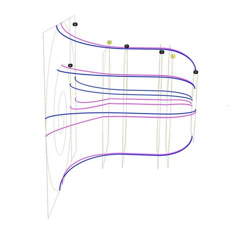
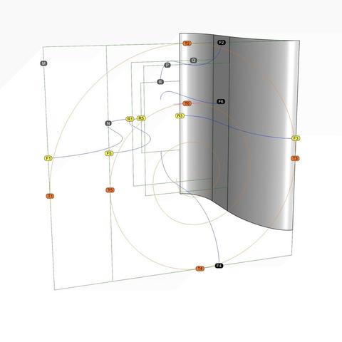
#IonicVolutes are the sinews of #IonicScrolls. Without #volutes, there would be scrolls, but not #Ionic Scrolls. Each scroll starts with a volute in front and is modulated by as many as six volutes of different shapes and sizes as it reaches the back, with the scroll surface tightly hugging the volutes at each contact point in ALL 3 dimensions. This is a key point to remember before we start #reverseEngineering the first #primaryProfileCurves from old image scans. This diagram shows the #scaffolding we will construct using straight lines and rectangles, first in 2 dimensions, then place them front-to-back in 3 dimensions using precise markers, and finally scale and superimpose the volutes on this scaffolding. All of this will be done before we derive the primary profile curves from the image scans. How did I know about this scaffolding? I didn't. It is not documented anywhere that I'm aware of. I developed this after years of striving to derive the correct shape, and I hope that there are people who can still "see" things I might have missed and help improve the design. So, the actual process went like this: I drew outlines from 2D image scans in the top view, getting close to #Vignola's detailed sketches. Then, I did the same thing with image scans in the side view, and I found that the designs didn't line up. After several iterations, I got the designs to line up in both views, and it was obvious that the bell shape of the scroll would follow the large volute in the front. So, I used the large volute as a "rail" and tried to sweep the primary profile curves on one rail. Big mistake! The undulating shapes of the primary profile curves wobbled wildly on the single rail — The middle, 3/4, and back of the scroll were twisted out of shape! Instead of trying to #sweepOneRail, I decided to clamp down wobbling with another operation called #sweepTwoRails, using volutes at both front and back ends as rails with less wobbling. You will need a #CAD tool to practice.

Pixelfed
After we diligently sweep the remaining sections of the #scroll surface as described in https://pixelfed.social/p/Splines/794203007066866034, we get a complete surface ready for a quality check using a #surfaceAnalysis tool known as #environmentMapping.

Environment mapping is similar to #textureMapping that I used in https://pixelfed.social/p/Splines/790701780235593999 to give a marble look to a finished design, except that the purpose of an #environmentMap is not to create a finished design, but just to temporarily wrap an image on a surface to check it by "eye."

Here, we see the scroll surface with a polished gold environment map. For many uses, this surface is adequate. But if you are looking for perfection, you will not be able to ignore the #banding on the scroll surface, precisely at each interstitial location — There are 5 distinct bands from 6 #modulatingSpirals.

The banding is caused by our #tertiaryCurves which are #continuous over the scroll surface, but not #smooth. Mathematically speaking, the tertiary curves are not #continuouslyDifferentiable over their entire length. So, is it time for #quaternaryCurves and sweeping the scroll surface again, section by section?

There is an easier way to achieve a smooth patina on the scroll surface using #surfaceBlend. We used #curveBlend, specifically #tangencyBlend in https://pixelfed.social/p/Splines/791723063470910081 and https://pixelfed.social/p/Splines/791794072490907090, and #arcBlend in https://pixelfed.social/p/Splines/792616677005177924.

To build the scroll surface using surface blends, we keep only the front 5 sections and the rear five section intact. That is because these sections are the most definitionally rich and impart the whole surface its distinctive look.

We discard the bands immediately adjacent to the front and rear bands — ones that are 14 units and 7 units deep. Then we split the remaining middle band that is 25 units deep into 18 and 7, with the larger section biased toward the front.
Splines (@[email protected])

Continuation of https://pixelfed.social/p/Splines/794199123072358090 After you have rebuilt all the #spiral arcs as well as the projected #secondaryCurves into #tertiaryCurves, it is finally time to sweep the scroll surface, but remember to do it one section at a time. Use one section of a spiral arc and the corresponding arc in the next interstitial as #railCurves. Then, #sweepTwoRails, using one section of the tertiary curves on each end of the rails. This diagram shows 5 sections of the swept surfaces in front and 5 sections in the back. The remaining ones will be built similarly but require further processing to make the whole surface smooth.

Pixelfed
The #secondaryCurves derived in https://pixelfed.social/p/Splines/793641134563617634 with 4 #modulatingSpirals are sufficient for a rough draft when #3DPrinting, but sweeping the scroll surface using these curves still causes subtle wobbles. These wobbles generate undercuts that precludes #CNCMilling with 3-axis machines depending on orientation, and that requires 5-axis #CNC machines instead.

To ameliorate that situation, I added 2 more interstitial frames labeled K and L, where k is 14 units in front of P, and L is 7 units behind Q. The size of K is 58.24 x 81.92 and that of L is 54.88 x 78.72. In other words, K is wider by 2.24 and taller by 1.92 compared to P and Q, while L is narrower by 1.12 and shorter by 1.28 compared to P and Q.

K is offset from P in the front view by 0.64 at top, 1.28 at bottom, 1.44 at left, and 0.80 at right. L is concentric with Q in the front view with top and bottom insets of 0.64 and left and right inset of 0.56. How I derived these is too complicated to discuss within #Pixelfed character limits.

Obviously, the scale factors for the spiral at K are 58.24/112 in X direction and 81.92/128 in Y direction. The scale factors for the spiral at L are 54.88/112 in X direction and 78.72/128 in Y direction.

So, using these 6 modulating spirals, we again identify the tangent points with their respective frames and #project straight lines through these points on the scaffolding surface to get 6 higher-accuracy secondary curves.

The diagram shows 6 blue #primaryCurves we extracted from #imageScans in https://pixelfed.social/p/Splines/793169876757012827 and https://pixelfed.social/p/Splines/793215298082967733 along with 6 new magenta secondary curves. The outlines we extracted from #Vignola’s antique images in 2-dimensions finally leap into 3-dimensions in a modern #CAD tool.

The blue primary curves are no longer needed for this design, but don't discard them. They are beautifully proportioned and can be used in other designs.
Splines (@[email protected])

Perspective view of #scroll #scaffolding to create #secondaryCurves from #primaryCurves. See https://pixelfed.social/p/Splines/793597613908557570 for backstory. Green rectangles M, N, P, Q, and R are shown with orange #volute #spirals non-uniformly scaled for their respective frames. Original spiral inside M is unchanged. To reduce clutter, I show only two sides and two primary curves, F2-R2 and F3-R3. Neither of these curves touches any of the volutes at any point, but they are used as #walkingSticks to create the surfaces which help us locate the tangent curves. To accomplish that, first locate all tangent points for orange spirals and their respective green frames. I labeled those for the largest spiral in an earlier post as T1 through T6. Here, I show only T2 and T3. The other points of tangency for the top and right sides can be seen if you follow the thick green lines. I didn't label them to reduce clutter, but each endpoint and each kink is a point of contact and tangency between a spiral and its frame. Our goal is to shift F2 to T2 and F3 to T3, with similar shifts at each point of tangency on the green line. To do that, #project the green line through T2 on the top surface to get the magenta curve on top. Think of the green line as a thin "rope" on which you shine a bright light from top to get the magenta line on the top surface. Both, the green and magenta lines touch the volutes, but neither touches the blue line at any point. Additionally, the top magenta line touches the top surface at EVERY point. When the blue line through F2 and the magenta line through T2 are viewed from a side, they are indistinguishable. We have found a secondary curve faithful to a primary curve. Using the same approach, project the green "rope" passing through T3 on the side surface to obtain the secondary magenta curve passing through T3. Blue primary curves and green straight lines have served their purpose and are no longer needed. Repeat for tangents on other sides.

Pixelfed
#SeeFeelTouchHug

In both #art and #engineering, one must be able to both #see and #feel things that might not be there (yet).

We were able to "see" the outlines of the #scroll surface from #imageScans of #Vignola's sketches in https://pixelfed.social/p/Splines/793169876757012827 and https://pixelfed.social/p/Splines/793215298082967733.

Vignola's images are on a 2-dimensional surface, as are the outlines we extracted from them. We believe the scroll surface also exists, but it is not yet manifest in 3-dimensional space. So, like a visually impaired person, we try to "feel" our way to the scroll surface using the outlines as our #walkingStick.

This diagram is identical to that in https://pixelfed.social/p/Splines/793493316852849994 but with the rear ends of the horizontal #primaryCurves marked with R1, R5, and R3, which are paired with F1, F5, and F3, respectively.

We know that the scroll surface must #touch the tangent points T1, T2, and so on in front, as well corresponding tangent points in the rear (not shown here to reduce clutter).

In https://pixelfed.social/p/Splines/792906324854792619, I mentioned that a scroll starts with a volute in front and is #modulated by as many as six volutes of different shapes and sizes as it reaches the back, with the scroll surface tightly hugging the volutes at EACH contact point in ALL 3 dimensions. In other words, it is not sufficient for the scroll surface to "touch" the #volute #spirals just in the front and rear. It must also "hug" the intermediate #modulatingSpirals. I will first show this technique with 4 modulating spirals using rectangles M, N, P, Q, and R as their frame, and add more later on.

Intuitively, we know that if we use curve F3-R3 as our walking stick on the straight vertical extrusion of that curve, we will feel the scroll surface *somewhere* on that extrusion along every point from front to back. We can narrow it down further by excluding portions above and below as we approach rectangle R in the rear.
Splines (@[email protected])

#ReverseEngineer #ImageScans We now dig into the archives and resurface old sketches for #restoration. This one is from #Vignola's #RegolaArchitettura at https://archive.org/details/gri_33125008229458/page/n39/mode/2up. This lavishly illustrated book with copious notes that also flaunt his #calligraphy was written (in Italian) when America was still a British colony. The book went out of copyright a long time ago. Straighten the image as much as you can in an image editor and crop it before bringing it into a #CAD tool. Then, stare at the image for a while and squint occasionally until you "see" crucial features and patterns emerge, while ignoring the "noise." Finally, try #curveFitting with the simplest of curves — straight lines, circular arcs, ellipse, and so on to get as close an approximation as possible. Remember that with hand-drawn sketches, the fit will rarely be perfect. So use some structure as a guide or #scaffolding as I laid out in https://pixelfed.social/p/Splines/792966507797633558. In the top left of the diagram, I show the measurements that I was satisfied with after a lengthy process of trial and error because the numbers comport with my understanding of the proportions the original designers intended — many, but not all of which are documented in #Scarlata's #PracticalArchitecture with #VignolaProportions in tabular form. For measurements that are missing, use plausible heuristics to fill in the blanks and try to justify your choices using simple rules. In this case, the bedrock rules are: 1. The entire #volute is exactly µ = 144 units wide, including #ArcZero, which extends 32 units beyond the portion of the volute that is actually used in the design. 2. The portion of the volute that is actually used in the design is 112 units wide, same as the height of the unadorned #capital. 3. Width of the #scroll bell shape as seen from the bottom is 112 units in front, 56 units in the middle and 28 units in the rear — all in #geometricSequence.

Pixelfed