#Modillion for the #ModernIonicEntablature

In https://pixelfed.social/p/Splines/790782316675150160 , I mentioned that there are two variations of the #IonicEntablature — a classic version that we saw in https://pixelfed.social/p/Splines/804548474524642209, and a modern version that has a new feature called #modillions, which are projecting brackets under the #corona of the #cornice. Note that, "modern" is a relative term. For designs that are more than 2000 years old, even an alteration hundreds of years ago would qualify as modern.

The modillion design continues a similar pattern but not identical to that of a #keystone. The measurements can be found in https://babel.hathitrust.org/cgi/pt?id=mdp.39015031201190&view=1up&seq=45 from which you can surmise that the length is 130 units (based on µ = 144) and the height is 36 units excluding the flamboyant #cymaReversa. The depth is not given, but can be derived from the sketch in https://babel.hathitrust.org/cgi/pt?id=mdp.39015031201190&view=1up&seq=141.

The measurements for the cymaReversa are listed between the corona and medallions, but its #profileCurve is attached to the modillion, not to the corona. Like #dentils, we attach modillions separately to the entablature. The dentils are still there with the same square footprint and same interdental spacing, but they are shorter to make room for the modillions above.

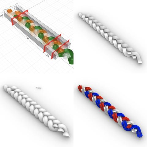
The original #volute that forms the basis of the modillion design is µ = 144 wide (including #arcZero) and 128 tall. Since the modillion height divides evenly into µ, I used that orientation for constructing the modillion, creating a box 144 units wide and 520 units tall. After construction, I scaled it to 1/4 to get 36 x 130 units, and then rotated it 90°.

The length of 520 was divided into 128*3.5 = 448 for the curved portion (which aligns with the wall) and 72 for the straight portion, which faces the front. Try to recreate it on your own first, and if you need help, just ask me.
Splines (@Splines@pixelfed.social)

There are two variations of the #IonicEntablature. The classic variation has #dentils, which are teeth-like structures shown here above the #frieze. The modern version has #modillions, which are projecting brackets under the #corona of the #cornice. Well, "modern" is a relative term. For designs that are more than 2000 years old, even an alteration 1000 years ago would qualify as modern. Although the sketch shows the #entablature with a square footprint, in practice, it runs the entire length of a #colonnade (multiple columns) or an #arcade (multiple arches). #CAD construction of the entablature is very similar to that of a #pedestal. The first step is to consult #Vignola's #RegolaArchitettura for the visual appearance, and then consult #Scarlata's #PracticalArchitecture for #VignolaProportions in tabular form. It is convenient to create a spreadsheet to convert the measurements given in Scarlata's book from module "parts" to your own model units based on your choice of value for the module parameter µ. Armed with these measurements, it is time to plot the points and draw the #primaryProfileCurves on our standard 2D grid with minor grid lines 8 units apart and major grid lines 32 units apart. In the first pass, skip the dentils and draw the profile curves for the rest of the moldings. Just as with the pedestal, I will show the macro-level plan as well as the detail plan. So, you don't have to go to Scarlata's book, but you know it's there if you want to. I will show the dentil arrangement in a subsequent post. Based on µ = 144, the classic Ionic entablature is 648 units (36 parts, or 4.5*µ) tall. Of this, the #architrave at the bottom is 180 units (10 parts, or 1.25*µ) tall, the frieze in the middle is 216 units (12 parts, or 1.5*µ) tall, and the cornice at the top is 252 units (14 parts, or 1.75*µ) tall.

Pixelfed
#3StrandBraids #FlowOnSurface

In the top-left, the highlighted magenta portion shows the interface between the #braids assembly and the #IonicScroll from https://pixelfed.social/p/Splines/795276076797088402.

Extract the #profileCurve shown as ABC in the top-right where the interface meets the scroll.

In https://pixelfed.social/p/Splines/794199123072358090, we rebuilt curves from 2nd-degree arcs to 3rd-degree NURBS for smoothness and swept the scroll surface one set of arcs at a time.

Now we have to flow braids on a single surface in one operation. So we need to combine the separate segments into a single NURBS curve. To do that, #explode the profile curve into individual segments, discard the straight portion, and join the curved portions.

Curves and surfaces have a #direction that you can change in the #CAD tool. Check that the direction of the joined curve is A to C, not C to A, and flip it if necessary. Then divide the curve at 120 units starting at A. This is marked by point B. Split the curve AC at B so that AB is 120 units long.

At this point AB is still made up of 5 segments, and exploding it would again decompose the curve into separate segments. So #rebuild AB as a single NURBS curve with 32 sections.

#Extrude AB to get a 48 units wide surface shown in magenta in the top-right. Point D is at the midpoint of AE and lies on the XZ plane.

Slice the channel assembly so that it is 8 units tall, 6 of which will be above the #tectonicSurface for the braid and 2 below. The tectonic surface is shown in the bottom-left as the flat magenta surface on the channel and the curved magenta surface for the scroll neck.

Flow the entire braid and channel assembly along the curved surface lining up points A, D, and E. For the vertical part on the side of the capital, just use the 33 unit tall block from https://pixelfed.social/p/Splines/799340150182400358 and bury 1 unit inside the #ovolo.

This concludes 3-strand braids. Only the non-essential #column #flutes remain.
Splines (@Splines@pixelfed.social)

After ensuring that the object in https://pixelfed.social/p/Splines/795271266191779399 is #airtight, extrude the front and rear planar surfaces by 1 part (8 units) on each end. At the end of this step, you should have a solid #scroll object with a smooth surface except for the flat parts that will butt against the head of the unadorned #capital. We have now concluded the #tectonic portions of the entire #IonicOrder. All that remains are decorative #eggsAndDarts that go on the #ovolo of the capital and the #3StrandBraid that goes on the scroll.

Pixelfed
#Braids #3StrandBraids

From the #profileCurve in https://pixelfed.social/p/Splines/798252244743520392, extrude a 192 units long solid starting at the origin.

Copy the original strand twice and place the copies 16 and 32 units to the right of the original. The three strands are shown here in orange, white, and green. Because of these shifts, the starting and ending portions of the braid are not usable. So use #cuttingSurfaces 40 units from the origin and 184 units from the origin. This will give you a clean 3-strand braid 144 units long.

For the #capital, we need two sections, one that is 120 units long and another that is 24 units long. So be prepared to split the braid-channel assembly one more time, but not yet.

Before making further cuts, make a copy of the entire 144 units-long braid assembly and save it separately. Then perform a #nonuniformScale with origin as the base point, and scale only in Z to shrink the height of channel from 12 to 6. The entire assembly will now have a height of 8.1 units down from 16.2. The nonuniformly-scaled version is not shown here.

The image on the top-right shows a rectangular profile curve sweeping the same rail curve as before, giving it sharp corners.

The image on bottom-left shows a profile curve derived from sections of the rail curve itself that were cut, rotated, and reflected to form a closed non-planar outline. When we sweep this closed curve on the original rail, we get smooth top and bottom surfaces and sharp edges on the sides.. After you sweep this shape, you will find that the ends are still open.

There is no way to close the holes with what we have discussed so far because the edges are not planar. To fix this, you will have to create #patchSurfaces using the edge curves of the profile on both ends and join all three surfaces. Check for #nakedEdges and #nonManifoldEdges for #airtight fit.

The last image shows a 5-point star with sharp angular lines swept on the same rail curve.
Splines (@Splines@pixelfed.social)

#Braids #3StrandBraids After we #sweepOneRail with the blue #sweepingCurve on the orange #railCurve for the #braid strand, we cap #planarHoles to get a single #airtight strand. As described in https://pixelfed.social/p/Splines/798015349727305297, the radius of the blue circle is 8 units, and the total height of a strand swept by that circle is 24 units. Half of that is above the #tectonic surface, which is still twice of what #Vignola documented in #RegolaArchitettura. We will apply #nonuniformScaling in the Z direction to reduce the height in half while keeping the length (X) and width (Y) the same. But before we do that we split and discard some of the bottom portion of the strand that is below the tectonic surface and is not needed. The top half of the figure shows the front view of a single strand. The bottom shows the perspective view of the same strand. Note that the orange braid rail starts at the center of the blue sweeping circle which looks like an ellipse in the front view. The orange rail itself looks like a flat sinusoid in the front view, but its beautiful meandering shape is really apparent in the perspective view. The orange rail curve is centered on the "ground" or XY plane, which is also where the #tectonicSurface for the braid is. The amplitude of the orange curve (maximum or minimum from axis of the curve) is 4 units. We need to preserve the geometry of the strand at least up to the bottom of the orange rail. If we split the strand exactly at 4 units below the ground plane, we hit a limit that not all #CAD tools are able to handle. To get around, we extend it past that limit by an arbitrarily small fraction, like 0.2, and discard the portions below. We could have extended it by 0.1 or 0.3 but it wouldn't have mattered. Next, we draw a profile curve for the braid channel which is 32 units wide and its groove is 12 units tall for now. The rims on both sides of the channel are each 8 units wide. Total height of rim and channel is 16.2 units

Pixelfed
Classic variation of the #IonicEntablature. Left side shows the macro-level plan. Right side shows the detailed plan for the #moldings.

All moldings should be familiar from the #IonicPedestal, except the #fascia — flat bands, of which there are 3, at the bottom of the #Architrave. The fascias grow progressively taller, starting at 36 units at the bottom, to 48 in the middle, and 60 at the top, with each successive one offset horizontally by 6 units from the previous one.

Above the fascia, we have a #cymaReversa which is 24 units tall and 20 units wide. Here we are using half turn of a helix with a vertical axis. Either helix or elliptical arcs are acceptable, but the choice must be consistent across the entire order. You cannot use ellipses in the pedestal and helices in the entablature, for example.

If you do use a helix, remember that it is a 3D shape like a round coil. To use it as a #profileCurve, it must be flattened to a 2D shape by #projecting it to the #constructionPlane. I will describe this technique in detail later.

The #frieze is a flat surface with no moldings. It is meant as a blank space on which to put custom decorative 3D #ReliefCarvings or sculptures.

There are no new moldings in the #cornice. Note that the order of #cymaRecta and cyma reversa are reversed from that of the #pedestal, with cyma recta at the top and cyma reversa at the bottom. The only difference between the two is that the recta has a horizontal axis and reversa has a vertical axis. Rotating either one 90° yields the other.

So, the bottom of the cornice starts with a cyma reversa 32 units tall and 34 wide. This is followed by a fascia 56 units tall on which the #dentils will appear later on. The 36 unit horizontal offset for the 4-unit thick fillet above it is to leave room for the dentils.

This is followed by a #reed (8 units), #ovolo (32 units), #corona (48 units), cyma reversa (16 x 12 units), fillet (4 units), cyma recta (40 x 44 units), and fillet 12 units
This shows the detailed measurements of the top and bottom portions of the #IonicPedestal. For macro-level measurements, see https://pixelfed.social/p/Splines/790571135473463588

Each of the blue curve segments (lines and arcs) that are marked with a yellow bubble is the #profileCurve for a #molding whose name is inside the bubble.

Starting at the bottom, we have a #plinth, a #fillet, a #cymaRecta, and a #reed as part of the #basement of an Ionic pedestal.

Next up, we have a #fillet and a #cavetto at the bottom of the #dado, and another cavetto and fillet at the top of the dado.

Moving higher up, a reed, an #ovolo, a #corona, a #cymaReversa, and a final fillet top off the cap of the pedestal.

They are called profile curves because each is the outline or silhouette of a 3D molding as seen from one side or in a cross section. In the case of a pedestal, these curves can be used directly to recreate the 3D shape of the pedestal. For this reason and in this case, I call them #primaryProfileCurves.

This is not always the case. For more complex shapes, such as the #scroll surface of an #IonicCapital shown in https://pixelfed.social/p/Splines/789956327130679640, the profile curves recovered by #reverseEngineering the image scans in #Vignola's book cannot be used directly to sweep the scroll surface because the scroll shape is not cylindrical. Like the inside of a rose, the scroll surface follows the outlines of spiral #volutes in the front and back, neither of which are circular. So, additional steps are necessary to derive the curves that we can actually use to reconstruct the surface.

In the case of the scroll surface, the derivation of these curves is not trivial and not obvious, but it is not difficult to understand, and no math is involved. There are multiple sets of curves, and each successive set is derived from a previous set. I call them secondary, tertiary, and quaternary curves.

For now, we stick with the primary profile curves for the pedestal.
Splines (@Splines@pixelfed.social)

This shows macro-level measurements for the #IonicPedestal. The key to #effectiveModeling is to simplify a complex shape into elementary components. Sometimes, this involves mentally flattening and reducing 3D shapes to 2D shapes, extracting elementary curves from them, and then recreating the 3D shapes from the extracted 2D curves. This is not always easy for organic shapes (which can still be approximated by Bézier curves). I extracted the #primaryCurves for the #IonicScroll surface in https://pixelfed.social/p/Splines/789956327130679640 after a lengthy trial-and-error process that involved #curveFitting images from #Vignola’s book, #RegolaArchitettura. I had to reverse engineer the details because the measurements have either been lost, or are locked away in some library. Web search yields no details on these measurements. Fortunately, for geometrical shapes like pedestals, this is very easy. Because of its square footprint, mentally slicing it through the middle from top to bottom, it is easy to “see” the outline. Another way to think about #curveExtraction is to shine an imaginary bright light on an object from behind in a dark room to reveal its silhouette. For the pedestal, even this silhouette or outline can be further reduced because the shape is symmetrical about the #columnAxis. With this realization, we only need to focus on one half of the outline, and methodically proceed from bottom to top, marking every kink and inflection point on the outline. Fortunately, the other authoritative book, #Scarlata’s #PracticalArchitecture, I mentioned in my introductory post already documents #VignolaProportions in tabular form. So we can skip everything else and go directly to that. Total height of #IonicPedestal is 864 units (108 parts, or 6*µ) of which the #PedestalBasement and #PedestalCap are each 72 units (9 parts, or µ/2) and the #Dado is 720 units (90 parts, or µ*5) tall.

Pixelfed

⬆️ #IonicPedestal #3DModeling

On the XY plane, centered on the column axis, draw a rectangle that is slightly taller than the #profileCurve and at least 3 times as wide as the maximum projection of the profile curve from column axis.

It must be ~3x because we need ~1.5x on each side. #Pythagoras said hypotenuse of a unit square is 1.414 units long.

In this case, the profile curve projects to 280 units from the column axis and is 864 units tall. So, I create a square that is 900 units in size.