The
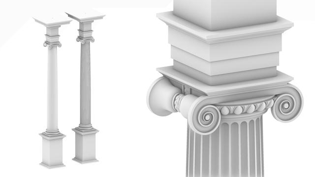
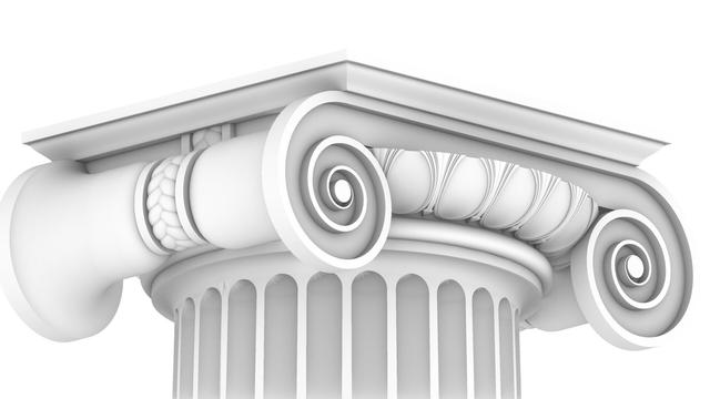
#Capital is the last essential component of the complete
#IonicOrder. The column
#flutes remain, but they are
#decorativeElements, and I will cover them later when I cover the decorative elements of the capital like the
#EggsAndDarts motif on the
#ovolo and the
#3StrandBraid on the ribbon or belt around the middle of the smooth
#scrolls.
The Ionic capital is complex, but not unapproachable. We will systematically construct everything in this draft rendering using just straight lines and arcs as promised in
https://pixelfed.social/p/Splines/789956327130679640, with the exception of the
#cymaReversa near the top and the 3-strand braid on the ribbon.
In this rendering, the cyma reversa near the top is made using a flattened half-turn of a
#helix, but it can also be constructed using elliptical arcs as I described in earlier posts.
The braid is a
#periodic shape with infinite variety and is also based on a helix. You can vary the number of strands, their thickness, pitch, and so on, none of which are essential to the Ionic Order itself. They're only a jumping point for further exploration.
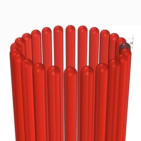
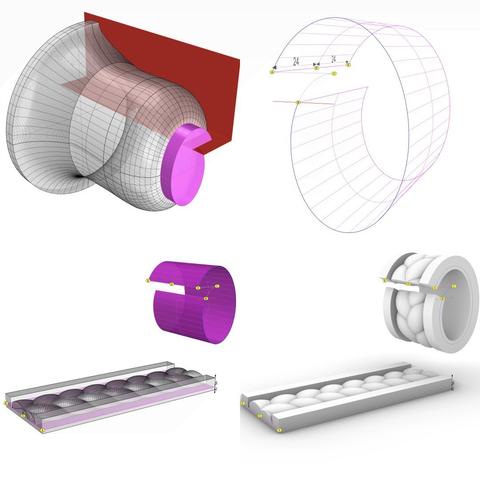
The eggs in the 'eggs and darts' motif can have different shapes. They can be convex like real eggs or concave as shown here, but the top is almost always sliced off. The total depth of the convex or concave shapes can vary, but only within a range of 1 part, or 8 units.
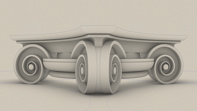
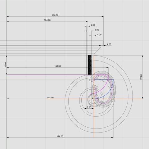
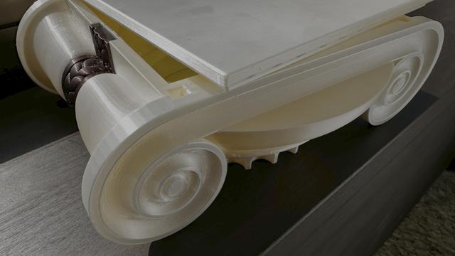
The
#volutes in the front and back of the capital are based on
#spiral shapes, of which there are many different kinds. Some have
#continuous curvature changes, while some do it in
#discrete steps, like
#fibonacci spirals that can approximate
#logarithmic spirals seen in nature, e.g., nautilus. When curvature changes are discrete, the spiral arms can diverge in
#arithmetic,
#geometric, or some other sequence.
We will construct all of these, and most notably the smooth, sweeping surface of the scrolls using just straight lines and arcs, and let the
#CAD software deal with delicate
#NURBS curves and surfaces.