Revolutionary #Volutes

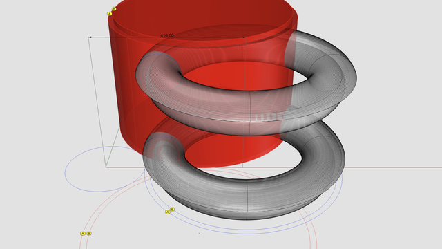
The two large blue circles at the bottom marked with A and B are from the floor plan for #ModernIonicCapital shown in https://pixelfed.social/p/Splines/807782440025967685. The larger one has a radius of 296 units, while the smaller one is 16 less, at 280. Both are centered at x = 416. Both are then rotated ±45° about the column axis to give us the four red circles. The small blue circle with radius 120 units is for the column neck.

The two red circles in the back are shown extruded vertically as cylinders. The other two haven't yet been extruded because we want to see the rest of the structure from the front.

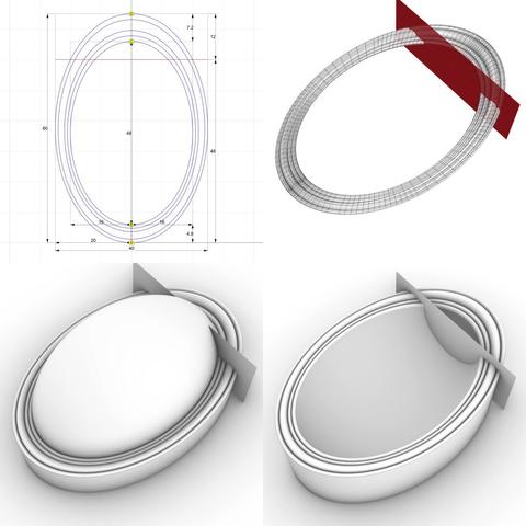
The two tube or #torus-like structures are obtained by revolving the trimmed #spiral #volute outlines from https://pixelfed.social/p/Splines/808043616946914228 about the vertical axis located at x = 416. Only the bottom tube maintains the interior shape of the spiral.

With this setup, vertically extrude the two remaining red curves in the front so they are at least as high as the top of the upper tube.

Next, perform a #booleanDifference between the top tube and the two extrusions marked A. Keep the wedge shape of the top tube on the left side and discard the remaining portion of the tube from the right.

Then, perform a boolean difference between the bottom tube and the two extrusions marked B. With the wedge shape of the bottom tube on the left side, perform a further #booleanIntersection with the two extrusions marked A. This will produce two curved spirals that are 16 units thick. Discard the remaining portions of the bottom tube as well as all the red extrusions.

After these operations, we are left with one wedge shape with curved faces and two spirals that are 16 units thick, also with curved faces.

The next step is to convert the outer surface of the wedge shape from convex to concave.
Splines (@Splines@pixelfed.social)

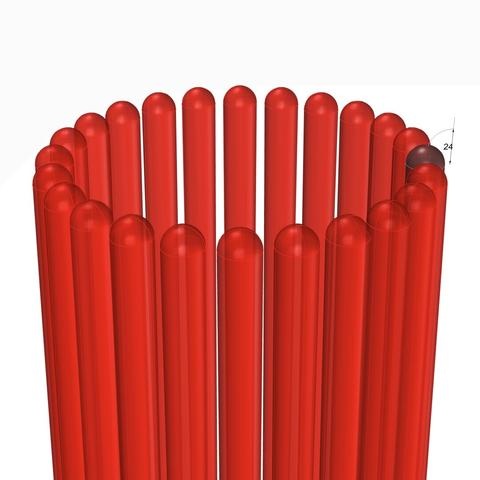
Plan for the #ModernIonicCapital If the design in https://pixelfed.social/p/Splines/807569519962747338 looks daunting, let me assure you it is far simpler than the work that went into the reconstruction of just the #scroll for the #classicIonicCapital. Be sure to check out #MileStone4 at https://pixelfed.social/p/Splines/795361973789834465. With the modern #IonicCapital, the designers went back to the basics of using just straight lines and circular arcs to define the geometry of the essential elements of the capital. No #braids, #keystones, or #modillions, and no #helix curves or #sinusoids. We start the floorplan for the modern ionic capital with a circle of radius 5/6 of µ (120 when µ = 144) which marks the neck of the #columnShaft. Tangent to this circle is a large circle of radius 296 units centered on the X axis exactly 416 units from the column axis. This is the circle that marks the curve of the #abacus, which is always tangential to the column shaft at the neck. This circle also marks the curved faces of the interior portion of the #volute wedge. Without the raised volute spirals, the interior wedge appears flush with the abacus as they follow the same circular arc. Concentric to this large circle is another circle with a radius of 280 units to mark the extent of the raised volute spirals which are 16 units thick. Another concentric circle of radius 266 units marks the outer edge of the top of the capital. The gap between the outermost large circle and the innermost concentric circle is 30 units, and that is reflected in another pair of circles centered on the column axis with radius of 250 units and 220 units to define the four corners. The capital footprint fits in a square 396 units wide — or 24.75 parts horizontally from axis, per #Scarlata in https://babel.hathitrust.org/cgi/pt?id=mdp.39015031201190&view=1up&seq=45. Use this with the sketch in https://babel.hathitrust.org/cgi/pt?id=mdp.39015031201190&view=1up&seq=142

Pixelfed
#IonicColumn #Flutes

In https://pixelfed.social/p/Splines/799864068250003272 I mentioned rounding off the radius of the bottom circle, but you don't have to. #CAD tools are perfectly happy working with 15.0728 or even higher precision as they are with 15.

After placing the two circles as described in that post, use the full #primaryProfileCurve of the shaft from https://pixelfed.social/p/Splines/791794072490907090 as a #sweepingRail and the two circles for the flutes as the #sweepingCurves, and #sweepOneRail for the body of a single flute. Close #planarHoles on both ends to get an #airtight solid.

Then draw a sphere at the center of the top circle using the same radius as the circle, and perform a #booleanUnion between the sphere and the flute body.

If you want a round bottom for the flute, repeat the sphere at the center of the larger circle using the same radius (15.0 or 15.0728) and perform another boolean union to get one flute.

Switch to the top view and make 24 copies of the flute (including the original) centered at the column axis and #group the 24 flutes.

Finally, perform a #booleanDifference with the flutes group on a copy of the solid #unadornedShaft to get a fluted variant.

The result is a column shaft with flutes carved out. Save the flutes separately for future reuse.

This concludes the entire #IonicOrder, including all #decorativeElements.

Now we pause and reflect: The whole exercise seemed like one of #art and #sculpture. Where is the #architecture in all of this?

Without a ceiling or a roof, there is no building. Without additional columns or walls, there is no ceiling. So, while we have completed the Ionic Order itself, we only have the first #buildingBlock — a single column.

Next step is to repeat the columns to create a #colonnade, which together with supporting walls or additional colonnades can support a ceiling.

Just like with everything else in design, there are rules of proportion for #intercolumniation, or space between columns.
Splines (@Splines@pixelfed.social)

#IonicColumn #Flutes This diagram shows the 2D geometry of an #Ionic #flute. The larger blue circle shows the flute outline near the #base of the #column. The smaller blue circle shows the flute outline near the #neck of the #shaft. Both subtend a 12° angle at the center of the column. Like an egg in the #EggsAndDarts motif, a flute must be centered on the column axis when viewed directly from the front, back, or the sides. This is why the 12° are split into 6° on either side of the X axis. The center of the larger circle is µ = 144 units from the origin on the X axis. The center of the smaller circle is 5/6 of µ, or 120 units from the origin. In https://pixelfed.social/p/Splines/799340150182400358, I mentioned working at sub-micron precision, and you might wonder where that came from when we have been using abstract units like µ without specifying any physical units. My apologies for not making it clear that I had assumed 1 unit was equal to 1 mm. If that assumption holds, then µ = 144 mm gives a total order height of 4104 mm, that is 13.46 ft. At smaller scales, the precision is even higher than 1/10 of a micron. With that said, here the radius of the larger circle is 15.0728 units and that of the smaller circle is 12.5606 units, with sub-micron precision if 1 unit = 1 mm. Refer to https://pixelfed.social/p/Splines/791399680747885646 and place the center of the smaller circle exactly at point J on the neck line. Later we will draw a sphere at the same location with the same radius. If you want a flat bottom for flutes, place the center of the larger circle at exactly 28 units (12 for the #fillet and 16 for the #cavetto or #conge) above point A in that figure. If you want a round bottom, then further move the larger circle up by the size of its radius. Nobody would quibble if you used a radius of 15 units instead of 15.0728 units, but it would make it easier to switch from flat to round bottom or vice-versa by simply moving the circle up or down 15 units.

Pixelfed
See https://pixelfed.social/p/Splines/796798349526747214 and https://pixelfed.social/p/Splines/796786779066451143 for detail.

Just like #ArcZero in the #spiral for the #IonicVolute, the plan for #EggsAndDarts starts out larger than what is eventually used.

The outermost frame is 7.5 parts or 60 units tall (from A to D), and 5 parts or 40 units wide when µ = 144. The innermost frame is 6 parts or 48 units tall (from B to C), and 4 parts or 32 units wide.

The height and width for both inner and outer are in 3:2 ratio. The difference in height is also split in the ratio 3:2. So, the gap between A and B as 12*2/5 = 4.8, and the gap between C and D as 12*3/5 = 7.2. We then divide both of these gaps in 5 equal segments shown by the dots between them.

Create an ellipse to fill the outer frame, and another to fill in the inner frame. Then interpolate them to create 4 more through the dots, only to delete the 3rd ellipse. This gives us the 5 #rails for sweeping the rim of the egg.

Create circles perpendicular to and touching adjacent pairs of rails, and then #sweepTwoRails using the circles to get the rim shown in the top-right. The red cutting plane marks tentative slicing for eggs.

The bottom left image shows a convex egg created with an #ellipsoid that is 48 units tall, 32 units wide, and 32 units deep. This is equivalent to #revolving the innermost ellipse around its major axis. Only half of this egg is above the oval slab.

The bottom right image shows the concave variant which is created by performing a #booleanDifference between the oval slab and the round egg created above. The top portion of the egg is removed in the concave variant, but the convex variant must still account for the bulge of a fully round egg. As such, the slab heights of the convex and concave variant are different. I will show the measurements later.

To create the slabs for the convex and concave variants, #extrude the outermost ellipse according to their measurements and #cap #planarHoles.
Splines (@Splines@pixelfed.social)

#Ovolo with a composite of both concave and convex eggs as seen from the bottom. For a perspective view, see https://pixelfed.social/p/Splines/796790115584241591. As I will show later, all of this is created using just straight lines and circular or elliptical arcs. Even though I used an oval as the starting point for the eggs, note their striking resemblance with natural eggs — with ends that taper off toward the bottom. This is due to the nature of the Ovolo surface, which is shaped like a bowl where the bottom radius is less than the top radius. So, when the egg is laid on this surface, it "flows" with the contours of that surface, and its bottom end is thereby tapered. Also note that in this view, the top of the eggs appear round, but they are in fact sliced, just like the rippled rim and the surrounding darts.

Pixelfed
#EggsAndDarts is a common classical design motif with endless variations, two of which are shown here — the top-left variant has convex eggs and the bottom-left variant has concave eggs. The sketch on the right shows the bottom view of the concave variant.

This motif is neither specific to the #IonicOrder, nor limited to the #ovolo of the capital. It is common to find it laid on linear #moldings like #cymaRecta or #cymaReversa of a #cornice.

The egg shape, the dart shape, the degree of convexity or concavity, and so on, are infinitely variable from subtle to pronounced. Designers are not limited to convex or concave, and it is possible to combine both in a single design. Also, it is not necessary to use the eggs and dart motif at all. There are infinite possibilities. However, when the eggs and darts motif is used, it is almost invariably sliced off at the top, as the bottom view of concave variant on the right reveals.

The concave version here is quite subtle, but a more pronounced version can be really eye-popping. I will show how to construct one using just straight lines and circular/elliptical arcs exclusively as I originally promised in https://pixelfed.social/p/Splines/789956327130679640.

As usual, we start with a flat 2-dimensional plan with lines and ovals to use as #sweepingRails. Then, we add circles and arcs as #sweepingCurves to define the cross-sections. After sweeping the cross section curves on the rails, we create the eggs.

Simply #revolve an ellipse on its major axis to get the convex version of an egg. To get the concave version of an egg, simply create a flat slab and perform a #booleanDifference on that slab using a convex egg.

Once we have all of this preparatory work done, we have to transfer the 3-dimensional design from the flat surface it was originally created on to the #doublyCurved surface of the Ovolo. This requires some elementary calculations using circle geometry.

Previous— https://pixelfed.social/p/Splines/795361973789834465
Splines (@Splines@pixelfed.social)

This sweeping shape is a timeless design that first appeared in the scrolls of the #IonicCapital as the most distinctive part of the #IonicOrder in classical Greco-Roman architecture more than 2500 years ago. Shown here with a zebra pattern on the wireframe of a CAD model to accentuate its features and attest to the smoothness of its 3-dimensional surface, the design has been refined many times since the original version over the last two millennia. The two most remarkable things about this design are that: — It can be recreated with modern CAD tools by drawing simple 2-dimensional straight lines and circular arcs exclusively. The end result is truly breathtaking and makes one wonder how architects visualized the result and put theory into practice. In the CAD model, the ultimate surface is a #NURBS surface that uses #BSplines extensively, but none of the B-splines or surfaces need to be created "by hand." One only has to draw straight lines and circular arcs with accurate measurements snapped to grids. — For a design that has survived the ages, it is lamentable how few authoritative sources that accurately describe fine details and exact reconstruction methodology remain accessible to the general public in the age of Internet. The most comprehensive is the 10-volume tome that Marcus #Vitruvius Pollio, a Roman architect and engineer, wrote for #JuliusCaesar and his successor Emperor #CaesarAugustus. [https://www.gutenberg.org/files/20239/20239-h/20239-h.htm] I frequently use two more authoritative sources: — "Regola delli cinque ordini d' architettura," or simply #RegolaArchitettura by Giacomo Barozzi da #Vignola [https://archive.org/details/gri_33125008229458/page/n3/mode/2up], and — "A Course in Theoretical and Practical Architecture," or simply #PracticalArchitecture by Francisco Salvatore #Scarlata (#Bordonaro), which documents #VignolaProportions in tabular form [https://babel.hathitrust.org/cgi/pt?id=mdp.39015031201190&view=1up&seq=5]

Pixelfed