#IonicColumn #Flutes

In https://pixelfed.social/p/Splines/799864068250003272 I mentioned rounding off the radius of the bottom circle, but you don't have to. #CAD tools are perfectly happy working with 15.0728 or even higher precision as they are with 15.

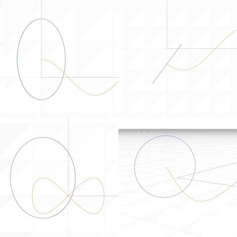
After placing the two circles as described in that post, use the full #primaryProfileCurve of the shaft from https://pixelfed.social/p/Splines/791794072490907090 as a #sweepingRail and the two circles for the flutes as the #sweepingCurves, and #sweepOneRail for the body of a single flute. Close #planarHoles on both ends to get an #airtight solid.

Then draw a sphere at the center of the top circle using the same radius as the circle, and perform a #booleanUnion between the sphere and the flute body.

If you want a round bottom for the flute, repeat the sphere at the center of the larger circle using the same radius (15.0 or 15.0728) and perform another boolean union to get one flute.

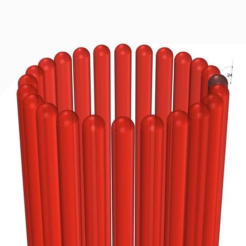
Switch to the top view and make 24 copies of the flute (including the original) centered at the column axis and #group the 24 flutes.

Finally, perform a #booleanDifference with the flutes group on a copy of the solid #unadornedShaft to get a fluted variant.

The result is a column shaft with flutes carved out. Save the flutes separately for future reuse.

This concludes the entire #IonicOrder, including all #decorativeElements.

Now we pause and reflect: The whole exercise seemed like one of #art and #sculpture. Where is the #architecture in all of this?

Without a ceiling or a roof, there is no building. Without additional columns or walls, there is no ceiling. So, while we have completed the Ionic Order itself, we only have the first #buildingBlock — a single column.

Next step is to repeat the columns to create a #colonnade, which together with supporting walls or additional colonnades can support a ceiling.

Just like with everything else in design, there are rules of proportion for #intercolumniation, or space between columns.
Splines (@Splines@pixelfed.social)

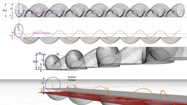
#IonicColumn #Flutes This diagram shows the 2D geometry of an #Ionic #flute. The larger blue circle shows the flute outline near the #base of the #column. The smaller blue circle shows the flute outline near the #neck of the #shaft. Both subtend a 12° angle at the center of the column. Like an egg in the #EggsAndDarts motif, a flute must be centered on the column axis when viewed directly from the front, back, or the sides. This is why the 12° are split into 6° on either side of the X axis. The center of the larger circle is µ = 144 units from the origin on the X axis. The center of the smaller circle is 5/6 of µ, or 120 units from the origin. In https://pixelfed.social/p/Splines/799340150182400358, I mentioned working at sub-micron precision, and you might wonder where that came from when we have been using abstract units like µ without specifying any physical units. My apologies for not making it clear that I had assumed 1 unit was equal to 1 mm. If that assumption holds, then µ = 144 mm gives a total order height of 4104 mm, that is 13.46 ft. At smaller scales, the precision is even higher than 1/10 of a micron. With that said, here the radius of the larger circle is 15.0728 units and that of the smaller circle is 12.5606 units, with sub-micron precision if 1 unit = 1 mm. Refer to https://pixelfed.social/p/Splines/791399680747885646 and place the center of the smaller circle exactly at point J on the neck line. Later we will draw a sphere at the same location with the same radius. If you want a flat bottom for flutes, place the center of the larger circle at exactly 28 units (12 for the #fillet and 16 for the #cavetto or #conge) above point A in that figure. If you want a round bottom, then further move the larger circle up by the size of its radius. Nobody would quibble if you used a radius of 15 units instead of 15.0728 units, but it would make it easier to switch from flat to round bottom or vice-versa by simply moving the circle up or down 15 units.

Pixelfed
#Braids #3StrandBraids

After we #sweepOneRail with the blue #sweepingCurve on the orange #railCurve for the #braid strand, we cap #planarHoles to get a single #airtight strand.

As described in https://pixelfed.social/p/Splines/798015349727305297, the radius of the blue circle is 8 units, and the total height of a strand swept by that circle is 24 units. Half of that is above the #tectonic surface, which is still twice of what #Vignola documented in #RegolaArchitettura.

We will apply #nonuniformScaling in the Z direction to reduce the height in half while keeping the length (X) and width (Y) the same. But before we do that we split and discard some of the bottom portion of the strand that is below the tectonic surface and is not needed.

The top half of the figure shows the front view of a single strand. The bottom shows the perspective view of the same strand.

Note that the orange braid rail starts at the center of the blue sweeping circle which looks like an ellipse in the front view. The orange rail itself looks like a flat sinusoid in the front view, but its beautiful meandering shape is really apparent in the perspective view.

The orange rail curve is centered on the "ground" or XY plane, which is also where the #tectonicSurface for the braid is. The amplitude of the orange curve (maximum or minimum from axis of the curve) is 4 units. We need to preserve the geometry of the strand at least up to the bottom of the orange rail.

If we split the strand exactly at 4 units below the ground plane, we hit a limit that not all #CAD tools are able to handle. To get around, we extend it past that limit by an arbitrarily small fraction, like 0.2, and discard the portions below. We could have extended it by 0.1 or 0.3 but it wouldn't have mattered.

Next, we draw a profile curve for the braid channel which is 32 units wide and its groove is 12 units tall for now. The rims on both sides of the channel are each 8 units wide. Total height of rim and channel is 16.2 units
Splines (@Splines@pixelfed.social)

#Braids #3StrandBraids With the #rail curve for a #braid strand in https://pixelfed.social/p/Splines/797916882329430160, we can start the construction of a braid that matches the sketch in #Vignola's #RegolaArchitettura shown in https://pixelfed.social/p/Splines/793215298082967733. The strands for this braid have a radius of 1 part or 8 units. So their diameter is 16 units, and the braid itself is 32 units wide. To create one strand, we start with a circle of radius of 8 units perpendicular to the tip of the orange curve. We use the orange curve as a #railCurve and the blue circle as the #sweepingCurve in the #sweepOneRail operation. Note that the circle appears distorted like an oval in all views — front view is on top-left, top view on top-right, right view in bottom-left, and perspective view in bottom-right. That is because the circle is perpendicular to the rail curve, not to any of the "world" coordinate planes. If the sweeping curve does not appear like an angled line in the top view, something is wrong. After the sweep, close #planarHoles to get a solid strand and, as always, check for #nakedEdges and #nonManifoldEdges to ensure an #airtight object. Refer again to the middle portion of the top diagram in https://pixelfed.social/p/Splines/793215298082967733 between the two bell shapes of the scrolls. The total width of the #tectonic surface on which the braid will be laid is 4 parts or 32 units wide. The braid has a rim 8 units wide on both sides that rises 6 units above the tectonic surface. Half of the braid should be above the tectonic surface, meaning that the total height of the braid should be 12 units. If you check the bounding box of this strand, you find that it is indeed 32 units wide as needed, but the height is 24 units. So we have to apply #nonuniformScaling to keep X and Y scale intact but halve the scale in the Z direction. This will reduce the roundness of the strand and cut its height in half to 12 as needed.

Pixelfed
#Braids #3StrandBraids

With the #rail curve for a #braid strand in https://pixelfed.social/p/Splines/797916882329430160, we can start the construction of a braid that matches the sketch in #Vignola's #RegolaArchitettura shown in https://pixelfed.social/p/Splines/793215298082967733.

The strands for this braid have a radius of 1 part or 8 units. So their diameter is 16 units, and the braid itself is 32 units wide.

To create one strand, we start with a circle of radius of 8 units perpendicular to the tip of the orange curve. We use the orange curve as a #railCurve and the blue circle as the #sweepingCurve in the #sweepOneRail operation.

Note that the circle appears distorted like an oval in all views — front view is on top-left, top view on top-right, right view in bottom-left, and perspective view in bottom-right. That is because the circle is perpendicular to the rail curve, not to any of the "world" coordinate planes. If the sweeping curve does not appear like an angled line in the top view, something is wrong.

After the sweep, close #planarHoles to get a solid strand and, as always, check for #nakedEdges and #nonManifoldEdges to ensure an #airtight object.

Refer again to the middle portion of the top diagram in https://pixelfed.social/p/Splines/793215298082967733 between the two bell shapes of the scrolls. The total width of the #tectonic surface on which the braid will be laid is 4 parts or 32 units wide. The braid has a rim 8 units wide on both sides that rises 6 units above the tectonic surface. Half of the braid should be above the tectonic surface, meaning that the total height of the braid should be 12 units.

If you check the bounding box of this strand, you find that it is indeed 32 units wide as needed, but the height is 24 units. So we have to apply #nonuniformScaling to keep X and Y scale intact but halve the scale in the Z direction. This will reduce the roundness of the strand and cut its height in half to 12 as needed.
Splines (@Splines@pixelfed.social)

#Braids #3StrandBraids We are finally ready to convert the two #sinusoids from https://pixelfed.social/p/Splines/797893262102038801 into a single 3D curve that captures the essential geometry of a #braid strand. First extrude the blue sinusoid into a surface that extends past the magenta sinusoid on both sides. Then draw a bounding box around the blue extrusion and trim the magenta sinusoid that falls outside the bounding box. Discard the bounding box, and extrude the trimmed magenta sinusoid into a surface that extends past the blue extrusion on both sides. Then split either surface with the other. It doesn't matter which surface is split and which is used as a cutting surface. The braid strand lies literally at the intersection of both surfaces. I trimmed the magenta surface with the blue one and deleted the top portion to reveal the curve at the intersection — shown here in orange. In perspective view this curve continuously swerves from left to right and simultaneously from top to bottom as it progresses along the X axis. This single curve has the characteristics of both sinusoids as seen in front and top views. In the side view, this looks like the #infinity symbol. So we have progressed from zero (with #helix), to plus (with #sinusoid), to infinity (with intersection of two #sinusoidal surfaces). Once we have this curve, we can sweep a circle around it to make a round strand. We can change the radius of the circle to make thinner or thicker strands. We can slant the circles to give a "calligraphic" look to the strands. We can use ovals, rectangles, squares, stars, or any closed shape to give different surface properties to the strands — the possibilities are endless. Once you have a closed #airtight strand with capped #planarHoles, make 2 more copies of the same strand. Shift the first copy by 1/3 the wavelength of the magenta sinusoid (48/3 = 16 units) and shift the second copy by 2/3 (48*2/3 = 32 units) while leaving the original one in its place.

Pixelfed
#IonicVolutes are the sinews of #IonicScrolls. Without #volutes, there would be scrolls, but not #Ionic Scrolls. Each scroll starts with a volute in front and is modulated by as many as six volutes of different shapes and sizes as it reaches the back, with the scroll surface tightly hugging the volutes at each contact point in ALL 3 dimensions. This is a key point to remember before we start #reverseEngineering the first #primaryProfileCurves from old image scans.

This diagram shows the #scaffolding we will construct using straight lines and rectangles, first in 2 dimensions, then place them front-to-back in 3 dimensions using precise markers, and finally scale and superimpose the volutes on this scaffolding.

All of this will be done before we derive the primary profile curves from the image scans.

How did I know about this scaffolding? I didn't. It is not documented anywhere that I'm aware of. I developed this after years of striving to derive the correct shape, and I hope that there are people who can still "see" things I might have missed and help improve the design.

So, the actual process went like this: I drew outlines from 2D image scans in the top view, getting close to #Vignola's detailed sketches. Then, I did the same thing with image scans in the side view, and I found that the designs didn't line up.

After several iterations, I got the designs to line up in both views, and it was obvious that the bell shape of the scroll would follow the large volute in the front.

So, I used the large volute as a "rail" and tried to sweep the primary profile curves on one rail. Big mistake! The undulating shapes of the primary profile curves wobbled wildly on the single rail — The middle, 3/4, and back of the scroll were twisted out of shape!

Instead of trying to #sweepOneRail, I decided to clamp down wobbling with another operation called #sweepTwoRails, using volutes at both front and back ends as rails with less wobbling.

You will need a #CAD tool to practice.