The Cloud-Burner: How to Master NVIS for Reliable Local Comms
1,593 words, 8 minutes read time.
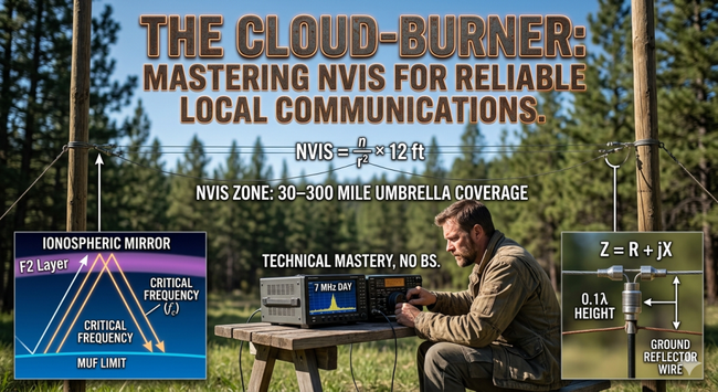
If you have just earned your Technician or General class license, you have probably already realized that the radio world is full of “dead zones.” You might be able to talk to a guy in Italy using a massive tower, or a guy across town using a local repeater, but what about the people two counties over? Often, that sixty to two-hundred-mile range is a “skip zone” where your signal just flies right over their heads. This is where Near-Vertical Incidence Skywave, or NVIS, comes in. Think of it as taking your radio signal and pointing it straight up at the sky, using the atmosphere like a giant mirror to bounce that energy right back down into your local region. It is the ultimate tool for keeping your community connected when the internet goes out or the repeaters fail. It doesn’t require a hundred-foot tower or a thousand-dollar antenna; it requires a little bit of wire, a low branch, and the willingness to learn how the air above your head actually works.
Understanding the Ionospheric Mirror
To get a handle on NVIS, you have to understand that the ionosphere isn’t just empty space; it’s a layer of the atmosphere filled with particles that have been “charged up” by the sun. We call this ionization. During the day, the sun is hitting these layers hard, making them thick and reflective. At night, they thin out. For NVIS to work, we need to pick a frequency that is low enough to be reflected back down rather than passing through into space. This is governed by something called the Critical Frequency, or $f_c$. If you try to send a signal straight up at a frequency higher than $f_c$, it’s gone forever. For new hams, the rule of thumb is simple: use the 40-meter band (7 MHz) during the bright part of the day, and move down to the 80-meter band (3.5 MHz) or 160-meter band (1.8 MHz) as the sun goes down.
The goal here is to keep your “angle of incidence” near ninety degrees. Imagine standing in a room with a flashlight and a mirror on the ceiling. If you shine the light at a sharp angle toward the wall, the light bounces off and hits the far corner of the room—that is your standard long-distance “DX” skip. But if you shine that flashlight straight up at the ceiling, the light bounces right back down onto your head. That is NVIS. By “burning the clouds” with your signal, you create a solid umbrella of coverage that fills in all those local gaps. The math behind this is surprisingly straightforward. The Maximum Usable Frequency (MUF) for your local area is roughly equal to that Critical Frequency because the “Secant” of your ninety-degree angle is essentially one:
$$MUF = f_c \cdot \sec(0^\circ) = f_c \cdot 1$$
When you stay below that $f_c$ limit, you ensure your signal doesn’t punch through the atmosphere and disappear. Instead, you get a reliable, high-strength signal that blankets your entire region, regardless of hills, buildings, or trees that might block a standard line-of-sight signal.
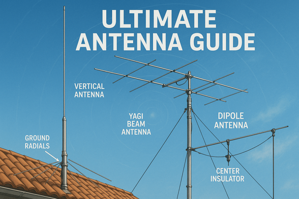
The Low-Hanging Wire: Your NVIS Antenna
The most common mistake new hams make with NVIS is trying to get their antenna too high. We are taught that height is king, but in the NVIS world, the ground is actually your friend. To push your signal straight up, you want a horizontal dipole antenna mounted very low—usually only 10 to 15 feet off the ground. When the antenna is this low, the radio waves that hit the ground reflect back up and join with the waves going toward the sky. This creates a massive “lobe” of energy pointing at the zenith. If you put that same antenna 50 feet in the air, the energy starts to focus toward the horizon, which is great for talking to Japan, but terrible for talking to the next town over.
When you build a low antenna, the “impedance” of the wire changes. Impedance, represented by the letter $Z$, is basically how much the antenna resists the flow of electricity from your radio. A standard dipole in free space is about 72 ohms, but when you bring it close to the dirt, that number drops. You might see your SWR (Standing Wave Ratio) jump around because the ground is “soaking up” some of that energy or reflecting it back into the wire. The formula for this total resistance looks like this:
$$Z = R_{rad} + R_{loss}$$
Your goal is to keep $R_{rad}$ (the energy actually leaving the antenna) high and $R_{loss}$ (the energy turning into heat in the dirt) low. You can help this by laying a “reflector wire” on the ground directly underneath your antenna. This acts like a mirror on the floor, bouncing even more energy up toward the sky and away from the dirt. It is a simple, cheap way to make a basic wire antenna perform like a professional military setup. It is about working smarter with the space you have, using the foundation of the earth to amplify your reach.
Operating with Discipline and Purpose
NVIS isn’t just about the gear; it’s about the man behind the mic. Because you are using lower frequencies like 40 and 80 meters, you are going to encounter a lot of noise. These bands are where lightning crashes and electronic interference from house appliances live. To be successful, you have to develop a “radio ear.” You learn to listen through the static for your brothers. You also have to be ready to change bands. If you’re talking on 40 meters and the signals start to fade as the sun sets, don’t just keep cranking the power. That is a waste of electricity and hard on your gear. Instead, understand that the ionosphere is changing. Be the leader who says, “The sun is going down, the critical frequency is dropping—let’s move the net to 80 meters.”
This kind of communication is a responsibility. In an emergency, NVIS is often the only thing that works when the cell towers are down and the repeaters have no power. As a new ham, mastering this technique means you are becoming a valuable asset to your family and your community. You aren’t just playing with a hobby; you are learning the physics of the atmosphere so you can provide a lifeline when it matters most. It takes patience to learn the cycles of the sun and the quirks of your local soil, but that discipline is what separates a true operator from someone who just bought a radio.
Take pride in the “bench time.” Build your own dipoles, experiment with different heights, and don’t be afraid to fail. Every time you tune an antenna or successfully make a contact two towns over during a storm, you are gaining technical mastery. You are learning to provide for those around you by using your mind and your hands. Keep your station clean, keep your character grounded, and remember that the strength of the airwaves comes from the discipline of the men who use them. Whether you are a Technician just starting out or a General looking to expand your skills, NVIS is the gateway to a whole new level of radio capability.
Looking Ahead: The Power of Local Links
The future of radio isn’t just in satellites or high-speed digital networks; it’s in the resilient, local links that we build ourselves. As you grow in this craft, you’ll find that NVIS is a bridge. It connects people across distances that are too far to see but too close for standard skip. It is a testament to the order of the world—that even the very air above us is designed in a way that allows us to reach out to one another. By mastering the “Cloud-Burner” technique, you are stepping into a long tradition of operators who value self-reliance and technical skill.
Continue to study the $SFI$ (Solar Flux Index) and watch how the bands open and close. Treat your fellow hams with respect and kindness, and always be willing to help the next new guy who is trying to figure out why his signal isn’t getting out. We are a community built on shared knowledge and a commitment to the craft. Stand tall, keep your wires taught, and we will see you on the air.
Call to Action
If this story caught your attention, don’t just scroll past. Join the community—men sharing skills, stories, and experiences. Subscribe for more posts like this, drop a comment about your projects or lessons learned, or reach out and tell me what you’re building or experimenting with. Let’s grow together.
SUPPORTSUBSCRIBECONTACT MED. Bryan King
Sources
- ARRL: Near Vertical Incidence Skywave (NVIS) Overview
- Electronics Notes: Understanding NVIS Propagation
- DX Engineering: Wire Antenna Building Basics
- NOAA: Real-Time Ionograms and Critical Frequency Data
- W8JI: NVIS Antenna Height and Ground Interaction
- QST Magazine: The Secret of NVIS Success
- HamRadio.me: Investigating NVIS Antenna Performance
- Navy-Radio: The AS-2259 NVIS Tactical Antenna
- Viasat: Tactical NVIS Systems and Applications
- Standardics: A Comprehensive Guide to NVIS Comms
- ScienceDirect: Ionospheric Refraction Physics
- Raymond Fowler: Practical NVIS for Amateur Operators
- Nonstop Systems: Extensive NVIS Bibliography and Research
- ITU: Prediction of NVIS Propagation Frequencies
- Ready for Ham Radio: NVIS for Emergency Preparedness
Disclaimer:
The views and opinions expressed in this post are solely those of the author. The information provided is based on personal research, experience, and understanding of the subject matter at the time of writing. Readers should consult relevant experts or authorities for specific guidance related to their unique situations.
#ZRJX #160MeterBand #40MeterBand #80MeterBand #amateurExtra #AmateurRadio #antennaEngineering #antennaHeight #antennaTuning #AS2259 #BenchCraft #Counterpoise #CriticalFrequency #CW #DLayerAbsorption #digitalModes #ElectromagneticRadiation #EMCOMM #emergencyCommunications #F2Layer #GeneralClass #GroundLoss #groundPlane #hamRadio #HorizontalDipole #impedanceMatching #ionosphere #MUF #NearVerticalIncidenceSkywave #NVIS #PlasmaFrequency #RadiationResistance #radioDiscipline #RadioNet #radioPropagation #Refraction #RegionalRadio #RFPhysics #SecantLaw #selfReliance #signalFading #signalToNoiseRatio #SkipZone #SolarFluxIndex #SSB #SWR #TacticalComms #TechnicalSovereignty #technicianClass #wireAntenna #ZenithRadiation