HOA Victory: How Indiana’s New Law Is Breaking the Silence for Future Radio Operators
1,502 words, 8 minutes read time.
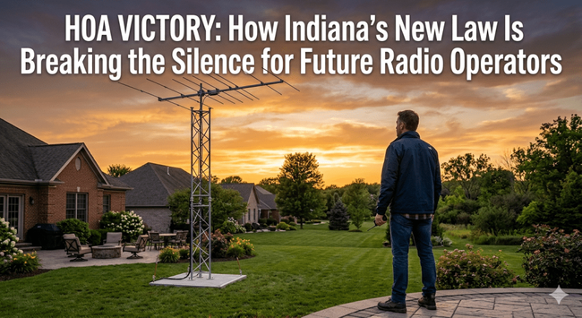
On March 12, 2026, Governor Mike Braun signed Indiana House Bill 1152 into law, marking a historic shift in the long-standing battle between amateur radio operators and homeowners associations. This legislation, which officially takes effect on July 1, 2026, prohibits HOAs from adopting or enforcing rules that flatly ban amateur radio antennas, towers, or feedlines. For decades, men across the country have put off pursuing their amateur radio licenses simply because they lived in deed-restricted communities where an outdoor antenna was a contractual impossibility. Indiana has now broken that stalemate by creating a legal framework where the utility of the Amateur Radio Service is balanced against neighborhood aesthetics. This move serves as a critical test case for other states, proving that common-sense protections for emergency-ready citizens can coexist with modern residential standards.
The core of this victory lies in how it addresses the “private contract” loophole that has historically left hams in the cold. While a federal ruling known as PRB-1 has long required local governments and municipalities to “reasonably accommodate” amateur radio antennas, that protection never extended to private homeowners associations. When you bought a home in an HOA, you effectively signed away your right to install an antenna, regardless of how much public good your radio station might provide during a blackout or natural disaster. Indiana’s new law changes the game by treating amateur radio equipment with the same level of respect already afforded to satellite dishes and flagpoles. It acknowledges that a licensed operator is not just a hobbyist, but a federally regulated asset who needs an external “ear” to the world to be effective.
For many men, the appeal of amateur radio is rooted in a desire for self-reliance and community service. Whether it is the technical challenge of bouncing a signal off the ionosphere or the satisfaction of being the only person in the neighborhood who can communicate when the cell towers fail, the hobby offers a unique blend of skill and utility. However, the fear of an HOA “cease and desist” letter has been a major deterrent. Indiana’s approach removes that barrier for future developments, stating that associations formed or documents created after June 30, 2026, cannot prohibit these vital installations. This forward-looking stance ensures that as new communities are built, the infrastructure for emergency communication is baked into the neighborhood rather than litigated out of it.
The importance of this development cannot be overstated when we look at the national landscape. For years, the American Radio Relay League has been pushing for federal legislation known as the Amateur Radio Parity Act. While that bill has seen various iterations in Congress, progress at the federal level has often been slow and bogged down by bureaucratic friction. Indiana decided not to wait for Washington. By passing HB 1152, the state has provided a “proof of concept” that state-level intervention is a viable path forward. It sends a clear message to other state legislatures: protecting the rights of radio enthusiasts is a win for public safety and a win for the individual liberty of homeowners who want to use their property to serve the greater good.
Understanding the technical necessity of an outdoor antenna is key to understanding why this law matters so much. A radio is only as good as its antenna, and physics is a stubborn mistress. While some hams try to hide wire antennas in their attics or run “stealth” setups that look like rain gutters, these are often compromises that severely limit the range and reliability of the station. In an emergency, a compromise antenna might be the difference between getting a distress signal out and sitting in silence. Indiana’s law recognizes that “effective” communication requires an “outdoor” presence. By protecting the right to have an external antenna and the feedlines that connect it to the radio, the law ensures that Indiana’s hams are operating at full capacity, ready to step in when traditional infrastructure fails.
The impact of this law also touches on the social fabric of the radio community. Amateur radio has always been a way for men to connect across geographic and social boundaries, sharing technical knowledge and forming “nets” that watch over their local areas. When an HOA bans antennas, it effectively silences these voices and prevents new members from joining the fold. By opening the door to antenna installations, Indiana is fostering a new generation of “Elmers”—the experienced operators who mentor newcomers. This law doesn’t just protect metal in the air; it protects the transfer of knowledge and the growth of a community that prides itself on being ready for anything.
Critics of such laws often worry about “antenna farms” devaluing property or creating eyesores. However, the Indiana legislation is a masterclass in compromise. It doesn’t give a ham carte blanche to build a three-hundred-foot tower in a quarter-acre backyard. Instead, it creates a standard of “reasonable” accommodation. This means that while an HOA cannot say “no” to an antenna, they can still work with the homeowner on placement and aesthetics, much like they do with satellite dishes. This collaborative approach lowers the temperature of the conflict. It moves the conversation from “you can’t do that” to “how can we make this work for everyone?” This is exactly the kind of blueprint that other states need to follow if they want to modernize their property laws without triggering a revolt from residential developers.
For those looking toward the future, the Indiana victory is a call to action. It demonstrates that when radio enthusiasts organize and present their case to lawmakers—emphasizing the public service, the technical education, and the emergency preparedness aspects of the hobby—they can win. The tide is turning against overly restrictive deed covenants that treat every outdoor structure as a threat to property values. People are beginning to realize that a home is more than just an investment vehicle; it is a place where a citizen should be able to exercise a federal license to help their neighbors. Indiana has set the pace, and now the eyes of the nation are on other state capitals to see who will be next to recognize the value of the amateur radio operator.
As we look at the broader significance of this law, it is clear that we are entering a new era of “Antenna Parity.” For too long, amateur radio was the only federally licensed service that lacked protection against private land-use restrictions. Television viewers got their rights in 1996 with the OTARD rules, and those who wanted to fly the American flag got their protections in 2005. It is only fitting that the men and women who provide the backbone of emergency communications finally receive their due. Indiana’s HB 1152 is not just a win for the “Hoosier State”; it is a beacon of hope for every prospective ham who has been waiting for the legal “all clear” to put up a mast and start talking to the world.
Call to Action
The time for sitting on the sidelines while your neighborhood association dictates your technical capabilities is coming to an end. Indiana has proven that with the right legislative push, the “HOA problem” isn’t an immovable object, but a hurdle that can be cleared with persistence and a focus on public safety. If you have been holding off on getting your Amateur Radio License because you were worried about where to put the antenna, now is the time to change your perspective. Use the momentum from this victory to start your journey; study the tech, understand the gear, and get ready for the day your state follows Indiana’s lead.
Take the first step toward self-reliance and community service by finding a local radio club or an online study group today. Whether you are interested in emergency preparedness, technical experimentation, or just the challenge of long-distance communication, your voice belongs on the airwaves. Don’t let a deed restriction define your reach—start preparing now so that when the towers go up in your neighborhood, you are ready to key the mic and join the global community of operators.
SUPPORTSUBSCRIBECONTACT MED. Bryan King
Sources
- Indiana General Assembly – House Bill 1152 Official Page
- Amateur Radio Newsline: Indiana Law Protects Ham Radio Antennas
- ARRL: The History and Status of the Amateur Radio Parity Act
- BillTrack50: Indiana HB1152 Summary and Action History
- Greyline Performance: HOA Antenna Legislation Resource Center
- FCC Guide: Over-the-Air Reception Devices (OTARD) Rule
- ARRL: Understanding PRB-1 and Municipal Limits
- South Whidbey Fire/EMS: Use of Radios in Neighborhood Emergencies
- LegiScan: Indiana House Bill 1152 Full Text and Progress
- Radio-Electronics: The Importance of Antenna Height and Placement
- Ready.gov: Building an Emergency Kit with Communication Tools
- Ham Radio Outlet: A Guide to Getting Your First License
Disclaimer:
The views and opinions expressed in this post are solely those of the author. The information provided is based on personal research, experience, and understanding of the subject matter at the time of writing. Readers should consult relevant experts or authorities for specific guidance related to their unique situations.
#AmateurRadio #amateurRadioParityAct #amateurRadioService #antennaSupportStructures #antennaTowerRegulations #atticAntennas #CivilDefense #communicationInfrastructure #communitySafety #deedRestrictions #emergencyCommunications #emergencyRadioNets #FCCRegulations #feedlines #frequencyCoordination #governorMikeBraun #groundingAndBonding #hamRadioAntennaLaws #hamRadioGear #HOAAntennaRestrictions #homeEmergencyPrep #IndianaHB1152 #legislativeVictory #LongDistanceRadio #neighborhoodAesthetics #neighborhoodAssociationRules #outdoorAntennaInstallation #PRB1 #preparednessMindset #privatePropertyRights #propertyValue #radioClubs #radioElmers #radioFrequency #RadioFrequencyInterference #radioLicensingForMen #radioStationSetup #radioTechnicalSkills #radioTowers #radioWavePropagation #residentialAntennaRights #selfReliance #signalReliability #skywavePropagation #stateLegislation #StealthAntennas #tacticalCommunication #UHFVHFAntenna