The Science Behind Radio Propagation: Understanding the Ionosphere
2,060 words, 11 minutes read time.
If you’re serious about becoming an amateur radio operator, understanding the invisible medium through which your signals travel is not just helpful — it’s essential. The ionosphere, that electrically charged region of Earth’s upper atmosphere, is where physics meets practical radio operation. Signals you transmit can bounce across continents or disappear without a trace depending on how well you understand this layer of our atmosphere. Grasping ionospheric science will give you a level of insight that separates the curious hobbyist from the skilled operator, and it’s knowledge that serves as a foundation for everything you’ll do behind the microphone.
The ionosphere is not a single, static entity. It is a dynamic, multilayered plasma affected by solar radiation, geomagnetic conditions, and the rhythms of day and night. Radio propagation through this region is a blend of science and art — where knowledge of physics directly informs practical decisions about frequencies, timing, and antennas. In this article, we will explore the ionosphere in depth, discuss its layers and their behaviors, explain the impact of solar activity, and examine how understanding these processes translates into better communication.
The Ionosphere: A Layered Radio Playground
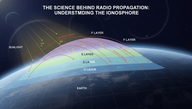
Rising roughly fifty kilometers above the surface of the Earth and extending up to 600 kilometers, the ionosphere is formed when solar ultraviolet light and X-rays strip electrons from neutral molecules, creating ions and free electrons. This process results in a conductive layer of plasma that interacts strongly with radio waves. Unlike lower layers of the atmosphere, where signals travel largely in straight lines, the ionosphere can bend, reflect, or absorb radio energy depending on its density and structure. This bending is what allows for long-distance skywave propagation, giving amateur operators the ability to reach locations far beyond the line of sight.
The ionosphere is divided into several layers, commonly known as the D, E, and F regions, each with distinct characteristics. The D layer, closest to Earth, exists from roughly 50 to 90 kilometers. It is a daytime phenomenon, heavily influenced by sunlight, and primarily acts as an absorber of lower frequency signals. The E layer, positioned between 90 and 120 kilometers, is more variable but can refract medium frequencies and, under certain conditions, sporadically refract higher frequencies as well. The F layer, extending from around 200 to 400 kilometers, is the most important for high-frequency (HF) communication. Its density and persistence allow signals to be refracted back to Earth over hundreds or thousands of kilometers. During the day, the F layer often splits into F1 and F2 sub-layers, recombining at night into a single F layer that sustains long-distance propagation after sunset.
Understanding these layers is crucial. The D layer’s tendency to absorb signals explains why lower frequencies are often unusable during the day. The E layer’s sporadic patches can create unexpected opportunities for local or regional contacts. The F2 layer, with its high electron density, is the workhorse of DX communications, capable of reflecting higher frequency HF signals around the globe when conditions are favorable. The interplay between these layers is complex, and conditions can change dramatically with time of day, season, and solar activity.
Day and Night: The Ionosphere in Motion
Time of day dramatically affects how radio waves propagate. During daylight, solar radiation increases ionization, particularly in the D and E layers. The D layer absorbs lower HF frequencies, making bands like 160 and 80 meters difficult or impossible to use for long-distance communication. The E layer, although less absorptive, can still interfere with certain frequencies. Meanwhile, the F layers become highly ionized, raising the maximum usable frequency (MUF) and enabling long-range contacts on higher HF bands. The result is a constantly shifting radio environment that requires operators to adjust their frequencies and expectations throughout the day.
At night, the situation changes dramatically. The D layer largely disappears, eliminating much of the absorption that hindered lower frequencies. This opens bands like 160 meters and 80 meters for night-time communication. The F layer remains ionized enough to continue reflecting HF signals, making DX contacts possible over much greater distances. Operators who understand these rhythms can strategically plan their activities, choosing the best bands at the right times and adjusting their antennas to maximize takeoff angles for long-distance propagation.
Seasonal variations also play a role. During winter, the ionosphere’s density is generally lower, which can affect the optimal frequency for a given path. Conversely, summer brings longer daylight hours and stronger D and E layer ionization, altering absorption patterns. Combined with the 11-year solar sunspot cycle, these factors create a constantly evolving propagation landscape. For an operator, this means learning to read the environment, rather than relying on fixed rules.
Solar Activity: The Ultimate Driver
Solar radiation is the primary energy source for the ionosphere, but not all solar activity is created equal. Ultraviolet (UV) and X-ray emissions from the sun ionize atmospheric molecules, creating the free electrons necessary for reflection. Sunspots, solar flares, and coronal mass ejections (CMEs) all impact ionization levels and, consequently, radio propagation.
The 11-year sunspot cycle, in particular, profoundly affects HF communications. During solar maxima, higher sunspot numbers mean increased UV radiation, greater electron densities in the F2 layer, and higher maximum usable frequencies. This is why bands like 15 meters or 10 meters, which may be dead during a solar minimum, can suddenly burst to life during the peak of the cycle. Conversely, during solar minima, electron density decreases, MUF drops, and operators must rely more heavily on lower frequencies for long-distance contacts.
Solar flares can also produce sudden, dramatic effects. When a flare strikes, the D layer can become intensely ionized, absorbing lower HF signals and causing temporary radio blackouts on affected paths. Geomagnetic storms triggered by CMEs can distort the F layer, creating unpredictable propagation paths or rapid fading. For the operator in training, understanding these solar influences is crucial for interpreting daily propagation forecasts and making strategic decisions about frequencies, antennas, and operating times.
Critical Frequency, MUF, and LUF: Making Sense of the Numbers
Two concepts dominate practical HF planning: the maximum usable frequency (MUF) and the lowest usable frequency (LUF). The MUF is the highest frequency that can be used on a particular path given the ionospheric conditions and antenna angles. Signals above this frequency will escape the ionosphere rather than being refracted back to Earth. The LUF, conversely, is determined by absorption, particularly in the D layer, below which signals are too weak to be useful. Between these two thresholds lies the optimal operating range for any given path and time.
The critical frequency is closely related: it represents the maximum frequency that can be reflected vertically by a layer. Operators use critical frequency measurements, often provided in propagation forecasts, to estimate the MUF for oblique paths. By combining knowledge of critical frequencies, MUF, and LUF with local band conditions and takeoff angles, an operator can maximize their chance of making successful contacts, even under variable ionospheric conditions.
Antennas and Takeoff Angles: Launching Your Signal
Understanding the ionosphere is only half the battle. The geometry of your transmission — particularly the angle at which it leaves your antenna — greatly influences propagation. Low-angle radiation favors long-distance contacts by striking the F layer at the optimal angle for refraction back to Earth. High-angle radiation may result in short skip or even escape the ionosphere entirely. Choosing or designing antennas with suitable radiation patterns, along with adjusting height and orientation, allows operators to exploit the ionosphere’s characteristics effectively.
Multiple-hop propagation is another factor to consider. Signals can bounce from Earth to ionosphere multiple times, covering vast distances. While this can enable global communication, it also introduces variability. Each hop is influenced by layer density, absorption, and irregularities in the ionosphere, which can cause fading, signal distortion, or intermittent contacts. Experienced operators learn to anticipate these effects, adjusting frequency and timing to compensate.
Propagation Variability: Expect the Unexpected
Despite sophisticated models and forecasts, the ionosphere remains unpredictable. Traveling ionospheric disturbances, geomagnetic storms, and sporadic-E events can create unexpected propagation opportunities or challenges. Multipath interference can reinforce or cancel signals, creating strong or weak reception at the same time in different locations. The variability of the ionosphere makes real-world experience critical. Logging contacts, noting signal strengths, and correlating observations with solar and geomagnetic conditions helps operators build intuition that no model can fully replicate.
Experimentation and observation are therefore essential. Operators who track the results of different frequencies, antenna orientations, and times of day gradually develop a mental map of how the ionosphere behaves under various conditions. This knowledge becomes an invaluable asset, allowing the operator to make informed decisions and optimize their communication strategy in real time.
Learning From the Science: Practical Applications
For anyone training for a license, ionospheric science is more than theory — it’s practical guidance. Knowing which bands are likely to be active at what times helps avoid wasted effort and maximizes successful contacts. Understanding solar cycles and sunspot activity allows operators to anticipate long-term propagation trends. Awareness of absorption, refraction, and reflection patterns guides antenna selection and deployment. Most importantly, familiarity with these principles fosters a mindset of curiosity and experimentation that underpins all great amateur radio practice.
Integrating this knowledge with modern tools, such as MUF maps, solar flux measurements, and real-time propagation reports, empowers the operator to plan effectively. Beyond mere technical competence, it cultivates strategic thinking and adaptability — traits that define skillful, confident radio operators.
The Art and Science of Becoming a Skilled Operator
Mastering ionospheric propagation is a journey, blending scientific understanding with practical experience. It requires patience, observation, and a willingness to learn from both success and failure. The ionosphere is not static, and no single formula guarantees a contact. Instead, proficiency comes from continuously adapting to a dynamic environment, experimenting with frequencies and antennas, and learning to interpret the subtle signals of a shifting atmosphere.
The reward is significant. Once you internalize the behavior of the ionosphere, you can reliably communicate over distances that once seemed impossible. You gain an intuitive sense of when to operate, which bands to use, and how to optimize your setup for long-distance contacts. That knowledge transforms radio from a mere hobby into a technical and strategic craft, where skill and insight translate directly into successful communication.
Conclusion: Speak the Language of the Sky
In the end, understanding the ionosphere is not just academic; it is empowering. It allows you to anticipate propagation patterns, select the right frequencies, adjust antennas for optimal takeoff angles, and respond intelligently to changing conditions. This knowledge is the foundation upon which every skilled operator builds, whether reaching across the county or around the world. By learning to read the rhythms of the ionosphere, you gain not just technical competence but a deeper appreciation for the invisible forces that connect us across vast distances.
Radio propagation is a dialogue with the sky. The more fluently you understand its rules and tendencies, the more effectively you can participate in that conversation. Mastering the science of the ionosphere transforms every transmission from a shot in the dark into a calculated, intentional communication — a skill that will serve you throughout your journey as an amateur radio operator.
Call to Action
If this story caught your attention, don’t just scroll past. Join the community—men sharing skills, stories, and experiences. Subscribe for more posts like this, drop a comment about your projects or lessons learned, or reach out and tell me what you’re building or experimenting with. Let’s grow together.
D. Bryan King
Sources
The Ionosphere – Humber Fortress DX Amateur Radio Club
The Ionosphere and Its Effect on Long‑Distance Communication – Ham Radio Academy
The Ionosphere and Skywave Propagation – ICO Optics
Atmospheric Layers & Their Effect on Radio Propagation – ICO Optics
Amateur Radio HF Communications – SARCNET
HF Propagation (presentation) – RCARC
Intermediate Amateur Radio Manual – G0HRS / G7OHO
Solar Activity and the Ionosphere – VU2NSB.com
BRATS QTH – Ionization & F Layer Ionisation
Ionospheric Radio Propagation Explained – AllElectroHub
AU‑18: Atmospheric and Ionospheric Propagation (Air University)
First Radar — CubeSat Transionospheric HF Propagation Observations
Direct Observations of Traveling Ionospheric Disturbances – arXiv
Simulation Study of HF Radio Waves Interacting With the Ionosphere – arXiv
Maximum Usable Frequency (Wikipedia)
Disclaimer:
The views and opinions expressed in this post are solely those of the author. The information provided is based on personal research, experience, and understanding of the subject matter at the time of writing. Readers should consult relevant experts or authorities for specific guidance related to their unique situations.
#10Meters #15Meters #160Meters #20Meters #40Meters #80Meters #AmateurRadio #amateurRadioHobby #amateurRadioLearning #amateurRadioTips #antennaOptimization #antennaRadiation #bandSelection #DLayer #DLayerAbsorption #daytimePropagation #DXCommunication #DXPathPrediction #ELayer #ELayerRefraction #electronDensity #FLayer #FLayerReflection #F2Layer #frequencySelection #geomagneticStormEffects #geomagneticStorms #hamRadioScience #HFAntennaPlanning #HFBandPlanning #HFBands #HFCommunication #HFCommunicationTechniques #HFContactStrategy #HFOperatorInsight #HFPathPlanning #HFPathPrediction #HFPropagationGuide #HFPropagationTechniques #HFSignalAnalysis #ionization #ionosphere #ionosphereKnowledge #ionospherePhysics #ionosphereVariability #ionosphericDisturbance #ionosphericExperiment #ionosphericForecast #ionosphericIrregularities #ionosphericLayers #ionosphericObservation #longDistanceDX #longDistanceRadio #longHaulRadio #lowestUsableFrequency #LUF #maximumUsableFrequency #MUF #multipathFading #nighttimePropagation #plasmaLayer #propagationEducation #propagationExperience #propagationForecasting #propagationObservation #propagationPatterns #propagationScience #propagationStudy #propagationTiming #radioAbsorption #radioBlackout #radioExperiment #radioOperatorSkill #radioOperatorTraining #radioPropagation #radioScience #radioWaveBending #RFPropagation #signalFading #skipPropagation #skywaveDX #skywavePropagation #solarActivity #solarFlares #solarFlux #solarMaximum #solarMinimum #solarUVRadiation #solarDrivenPropagation #sporadicE #sunspotCycle #takeoffAngle #XRayIonization