The Power of the Whisper: How WSPR and WSJT-X are Redefining Long-Distance Radio

1,250 words, 7 minutes read time.

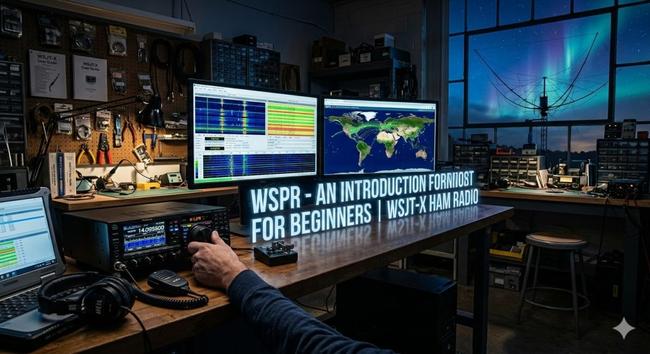
Amateur radio operators and technology enthusiasts are currently utilizing the Weak Signal Propagation Reporter, commonly known as WSPR, and the WSJT-X software suite to achieve global communication using minimal power. Developed by Nobel laureate Joe Taylor, K1JT, this digital protocol allows stations to send and receive signals that are often completely buried in background noise, making it possible to map atmospheric conditions and radio propagation in real-time. This technology serves as a critical entry point for men looking to understand the mechanics of the ionosphere and the efficiency of modern digital signal processing. By leveraging advanced mathematical algorithms, WSPR proves that high-power amplifiers and massive antenna towers are no longer the only way to reach across the ocean, offering a technical challenge that rewards precision and patience over brute force.

The core of this system lies in the software known as WSJT-X. This program implements several digital protocols designed specifically for making reliable communication under extreme conditions where traditional voice or Morse code signals would fail. While WSPR is not a conversational mode, it acts as a global beacon system. A station transmits a brief packet containing its callsign, location grid square, and power level. Thousands of other stations around the world, running the same software, listen for these signals and automatically report any successful decodes to a central internet database called WSPRnet. This creates a living, breathing map of how radio waves are traveling across the planet at any given second, providing invaluable data for anyone interested in the science of communication.

Understanding the physics behind this process is what separates a casual observer from a true radio technician. The Earth’s ionosphere, a layer of the atmosphere ionized by solar radiation, acts as a mirror for certain radio frequencies. Depending on the time of day, solar flare activity, and the season, these signals can skip off the sky and land thousands of miles away. In the past, confirming these paths required luck and high-power transmissions. Joe Taylor once noted that the goal of these modes is to utilize the information-theoretic limits of the channel. This means squeezing every bit of data through the smallest amount of bandwidth possible, allowing a station running only one watt of power to be heard in Antarctica from a backyard in Michigan.

For the man standing on the threshold of earning his amateur radio license, WSPR is the ultimate proof of concept. It removes the intimidation factor of “talking” to strangers and replaces it with a pure engineering objective: How far can my signal go with the least amount of effort? Setting up a WSPR station requires a computer, a transceiver, and a simple wire antenna. The software handles the heavy lifting of Forward Error Correction and narrow-band filtering. This process teaches the fundamentals of station grounding, signal-to-noise ratios, and frequency stability—skills that are mandatory for passing the licensing exam and, more importantly, for operating a professional-grade station.

The hardware requirements are surprisingly modest, which appeals to the practical, DIY-oriented mind. Many enthusiasts use a Raspberry Pi or an older laptop dedicated to the task. The interface between the radio and the computer is the critical link, ensuring that the audio generated by the software is cleanly injected into the radio’s transmitter. If the audio levels are too high, the signal becomes distorted, “splattering” across the band and becoming unreadable. This level of technical discipline is exactly what is required in high-stakes fields like aviation or telecommunications. Mastering the “clean” signal is a badge of honor in the ham radio community, signifying a man who knows his equipment inside and out.

As we look at the data generated by WSPR, we see more than just dots on a map; we see the pulse of the sun. Because radio propagation is tied directly to solar activity, WSPR users are often the first to notice a solar storm or a sudden ionospheric disturbance. When the sun emits a massive burst of energy, the higher frequency bands might “open up,” allowing for incredible distances to be covered on low power. Conversely, a solar blackout can shut down communication entirely. Being able to read these signs and adjust one’s strategy accordingly is a core component of the hobby. It turns a simple radio into a scientific instrument used for environmental monitoring.

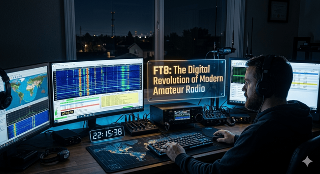
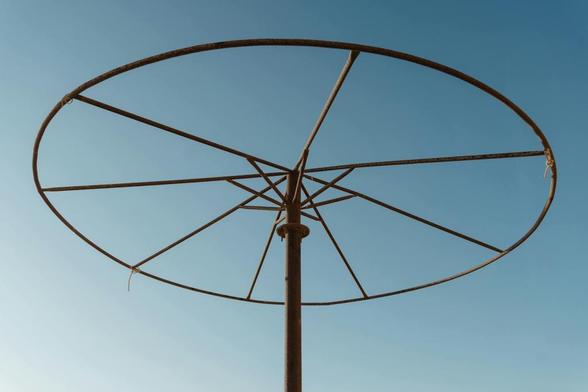
The community surrounding WSJT-X is one of rigorous peer review and constant improvement. The software is open-source, meaning the code is available for anyone to inspect and refine. This transparency has led to a rapid evolution of the protocols. While WSPR is for propagation reporting, other modes within the suite like FT8 or FST4 are used for rapid-fire contacts. However, WSPR remains the gold standard for testing antennas. If a man builds a new wire antenna in his yard, he doesn’t have to wait for someone to answer his call to know if it works. He can run WSPR for an hour, check the online map, and see exactly where his signal landed. It provides immediate, objective feedback that is essential for any technical project.

The future of this technology points toward even more robust communication in the face of increasing electronic noise. As our cities become more crowded with Wi-Fi, power lines, and electronics, the “noise floor” of the radio spectrum is rising. Traditional modes are struggling to compete. Digital modes like those found in WSJT-X are the solution, using digital signal processing to “dig” signals out of the static. This represents the next frontier of amateur radio—the transition from analog heritage to digital mastery. For those looking to get involved, the barrier to entry has never been lower, and the potential for discovery has never been higher.

In the broader context of emergency preparedness and global infrastructure, the lessons learned from WSPR are invaluable. In a scenario where satellites or internet backbones fail, the ability to bounce low-power signals off the atmosphere remains one of the only viable long-distance communication methods. A man who understands how to deploy a WSPR-capable station is a man who can provide data and connectivity when everything else goes dark. This sense of utility and self-reliance is a driving force for many who pursue their license. It is not just about a hobby; it is about mastering a fundamental force of nature to ensure that the lines of communication stay open, no matter the circumstances.

Call to Action

If this story caught your attention, don’t just scroll past. Join the community—men sharing skills, stories, and experiences. Subscribe for more posts like this, drop a comment about your projects or lessons learned, or reach out and tell me what you’re building or experimenting with. Let’s grow together.

D. Bryan King

Sources

  • WSJT-X Main Page: physics.princeton.edu/pulsar/k1jt/wsjtx.html
  • WSPRnet Official Site: wsprnet.org/drupal/
  • ARRL – What is WSPR?: arrl.org/wspr
  • K1JT’s WSPR Implementation Guide: physics.princeton.edu/pulsar/k1jt/WSPR_Instructions.pdf
  • WSPR on Raspberry Pi – GitHub: github.com/JamesP6000/WsprryPi
  • Make Magazine – Ham Radio for Beginners: makezine.com/projects/ham-radio-for-beginners/
  • Introduction to Digital Modes – OnAllBands: onallbands.com/digital-modes-101-wspr/
  • DX Engineering – WSPR Equipment: dxengineering.com/search/product-line/wsjt-x-interfaces
  • Radio Society of Great Britain – WSPR Intro: rsgb.org/main/get-started-in-ham-radio/digital-modes/wspr/
  • Ham Radio School – Digital Mode Basics: hamradioschool.com/digital-modes-introduction/
  • The History of WSJT-X – Princeton University: princeton.edu/news/2017/10/18/nobel-prize-winner-taylor-channels-passion-radio
  • WSPR Rocks – Real-time Database: wspr.rocks
  • Antenna Theory for Digital Modes: antenna-theory.com
  • HF Propagation Basics – NOAA: swpc.noaa.gov/phenomena/hf-radio-propagation
  • Digital Radio Mondiale and WSPR – IEEE: ieee.org/publications/wspr-technical-overview

Disclaimer:

The views and opinions expressed in this post are solely those of the author. The information provided is based on personal research, experience, and understanding of the subject matter at the time of writing. Readers should consult relevant experts or authorities for specific guidance related to their unique situations.

#amateurRadioCommunity #amateurRadioForBeginners #amateurRadioLicense #antennaTesting #AtmosphericScience #AtomicClock #Balun #bandwidth #CATControl #dataModes #Decibel #digitalModes #digitalSignalProcessing #dipoleAntenna #DIYRadio #DXing #ElectronicEngineering #Elmers #EmergencyCommunication #ExtraClass #forwardErrorCorrection #frequencyHopping #FrequencyStability #FT8 #GeneralClass #GlobalRadioMap #GPSTime #GridDownRadio #GridSquares #Grounding #hamRadio #hamRadioExamPrep #hamRadioGear #HamRadioMentoring #hamRadioProjects #hamRadioSkills #hamRadioSoftware #hfAntenna #HFRadio #HighFrequency #impedanceMatching #ionosphere #JoeTaylorK1JT #LongDistanceRadio #LowPowerRadio #MagneticLoopAntenna #MaidenheadLocator #NarrowbandCommunication #NetworkTimeProtocol #NoiseFloor #OpenSourceRadio #PCToRadioInterface #QRP #RadioAstronomy #RadioBenchmarking #radioCommunication #radioFrequency #RadioInterfacing #RadioNetworking #radioPropagation #RadioScience #radioSignals #radioSpectrum #radioTechnician #radioTroubleshooting #RadioWavePhysics #RaspberryPiRadio #RealTimeTracking #RFInterference #RigControl #SDR #shortwaveRadio #SignalDecoding #SignalReporting #SignalToNoiseRatio #softwareDefinedRadio #solarActivity #solarCycle #SolarFlareImpacts #SoundcardPacket #SpaceWeather #StandingWaveRatio #SurvivalCommunication #SWR #TechHobbiesForMen #TechnicalSelfReliance #technicianClass #telecommunications #timeSync #TransceiverSetup #Unun #verticalAntenna #VOXControl #WeakSignalPropagationReporter #wireAntenna #wirelessTechnology #wsjtX #wsjtXTutorial #WSPR #WSPRTutorial #WSPRnet

FT8: The Digital Revolution of Modern Amateur Radio

2,237 words, 12 minutes read time.

FT8 is a digital communication protocol released in 2017 by Joe Taylor, K1JT, and Steve Franke, K9AN, designed to allow radio amateurs to exchange contact information under extreme weak-signal conditions. Operating primarily on High Frequency (HF) bands, FT8 uses a precise 15-second sequence of structured data bursts to transmit call signs, signal reports, and grid squares even when the human ear can hear nothing but static. This mode has fundamentally shifted the landscape of ham radio by enabling reliable global communication during the low points of the solar cycle, ensuring that operators can maintain “workable” signals despite poor ionospheric propagation. Its rapid adoption stems from its efficiency and the fact that it allows modest stations with simple wire antennas and low power to compete with massive “big gun” contest stations.

The technical backbone of FT8 is a specialized form of digital modulation known as 8-slot Frequency Shift Keying (8-FSK). This means the signal shifts between eight distinct tones, each representing a specific piece of data. Because the bandwidth is incredibly narrow—only 50 Hz—multiple conversations can happen simultaneously within a standard 3 kHz single-sideband radio channel without interfering with one another. To make this work, the protocol requires absolute synchronization. Every participating computer must have its internal clock set to within one second of Coordinated Universal Time (UTC). This allows the software to know exactly when to start listening for a message and when to begin transmitting its own response. Without this temporal precision, the sequence breaks down and the data becomes unreadable noise.

The “how” of FT8 is a masterclass in forward error correction and data compression. A standard FT8 message is only 75 bits long, yet it contains everything necessary to confirm a legal and valid contact. Joe Taylor, a Nobel Prize-winning astrophysicist, applied the same principles used to detect faint signals from deep space to the world of amateur radio. By using sophisticated algorithms, the software can reconstruct a message even if a significant portion of the signal is lost to fading or atmospheric interference. This capability allows FT8 to function at signal-to-noise ratios as low as -21 dB. To put that in perspective, an FT8 signal can be decoded when it is significantly weaker than the background noise of the universe itself.

The impact of this mode on the hobby cannot be overstated. Before FT8, many men found themselves frustrated by “dead bands” where hours of calling “CQ” yielded no results. FT8 turned the hobby into a 24/7 pursuit. According to the ARRL (American Radio Relay League), FT8 and its successor modes now account for a massive percentage of all amateur radio activity globally. It has bridged the gap between traditional radio technology and modern computing, appealing to men who enjoy the technical challenge of optimizing a digital interface while still respecting the core physics of radio wave propagation. It is the tool of the modern digital woodsman, carving out a path through the noise of a crowded spectrum.

The Mechanics of the 15-Second Cycle

Understanding the rhythm of FT8 is essential for any man looking to master the digital airwaves. The protocol operates on a rigid 15-second “time slot” system. In the first 12.64 seconds of a slot, the message is transmitted; the remaining time is used for the software to process the data and for the operator to prepare the next response. This “even/odd” sequence ensures that two stations aren’t talking over each other. One station transmits on the even-numbered minutes and 15-second intervals, while the other listens, then they swap. This disciplined structure removes the guesswork and chaos often found in voice or Morse code pile-ups, creating an orderly flow of information that maximizes the use of available airtime.

To get on the air with FT8, an operator needs more than just a radio and an antenna; he needs a bridge between the analog and digital worlds. This is usually achieved through a dedicated USB interface or a built-in sound card in modern transceivers. The software—most commonly WSJT-X—takes the digital data from the computer, converts it into audio tones, and feeds those tones into the radio’s transmitter. On the receiving end, the process is reversed. The radio “hears” a series of chirps and warbles, which the sound card captures and the software decodes back into text on the screen. This synergy of hardware and software is what makes FT8 a true “hybrid” mode of communication.

The software interface provides a “waterfall” display, a visual representation of the radio spectrum where signals appear as vertical blue or yellow streaks. This allows an operator to see exactly where the activity is and find an open “slot” to transmit. It is a highly visual and tactical way to operate. Instead of spinning a dial and listening for a faint voice, you are scanning a digital landscape, looking for the telltale signatures of other stations. For many men, this adds a layer of strategy to the hobby that is deeply engaging, akin to a high-stakes game of electronic chess where the board is the entire planet.

Why Signal-to-Noise Ratio Matters

In the world of radio, the Signal-to-Noise Ratio (SNR) is the ultimate metric of success. It is the difference between the strength of the desired signal and the level of background atmospheric noise. FT8 excels because it is “wideband” in its ability to hear, but “narrowband” in its transmission. Because the tones are so precise and the error correction so robust, FT8 can pull a signal out of a “noise floor” that would render a voice transmission completely unintelligible. This is the primary reason why FT8 is the go-to mode for “DXing”—the art of contacting long-distance stations. It levels the playing field, allowing a man with a 100-watt radio and a wire in his backyard to talk to someone in Antarctica or Japan.

The mathematical genius behind FT8 involves a process called “Costas arrays” and “Low-Density Parity-Check” (LDPC) codes. These are not just buzzwords; they are the tools that allow the software to identify the start of a transmission and fix any bits that were flipped or lost during the journey through the ionosphere. As Joe Taylor noted in his technical documentation for the WSJT-X suite, the goal was to create a mode that was “optimized for the specific characteristics of HF propagation.” By focusing on short, structured bursts rather than long-form conversation, FT8 prioritizes the successful completion of a contact over everything else.

This efficiency does come with a trade-off. FT8 is not a “rag-chewing” mode. You won’t be discussing the weather or your favorite sports team. The messages are strictly limited to the essentials: call sign, signal report (in dB), and location (maidenhead grid square). However, for many men, the thrill is in the “catch.” The satisfaction comes from seeing a distant, rare station pop up on the screen and successfully completing that 60-second digital handshake. It is a hobby centered on the achievement of technical milestones and the collection of digital “QSL” cards that prove you reached the far corners of the earth.

Integration with Modern Computing

The rise of FT8 has coincided with the ubiquity of high-speed internet and powerful home computers. This integration has led to the creation of the “PSK Reporter” network, a massive, real-time map of global radio propagation. When your computer decodes an FT8 signal, it can automatically upload that data to a central server. This allows any operator in the world to see exactly where their signal is being heard in real-time. It is a revolutionary tool for understanding the ionosphere. A man can send out a few “CQ” calls and then check a website to see that he is being heard in Spain, Australia, and Brazil, all within seconds.

This real-time feedback loop has changed the way men approach radio. It removes the mystery and replaces it with data. If you aren’t being heard, you can immediately troubleshoot your antenna or wait for the bands to open up. This data-driven approach appeals to the problem-solving nature of the masculine mind. It turns amateur radio into a laboratory where the results are visible and measurable. You aren’t just shouting into the void; you are probing the atmosphere and receiving instant confirmation of your reach.

Furthermore, FT8 has fostered a global community of “citizen scientists.” By contributing data to these networks, ham operators are helping researchers understand solar cycles and their impact on global communications. As noted in various IEEE publications, the sheer volume of data generated by FT8 operators provides a unique look at the Earth’s upper atmosphere that was previously impossible to obtain on such a scale. When you engage in FT8, you aren’t just playing with a radio; you are part of a global sensor network that monitors the very fringes of our planet’s environment.

The Role of Precision Timing

As mentioned, timing is the lifeblood of FT8. Because the protocol relies on such tight windows of transmission, even a two-second drift in your computer’s clock can make you invisible to the rest of the world. This has led to the widespread use of time-synchronization software like Dimension 4 or Meinberg NTP. For the radio enthusiast, this adds another layer of technical “shack” maintenance. Ensuring that your station is perfectly synced to the atomic clocks in Colorado or via GPS is a point of pride. It represents the discipline required to participate in high-level digital communications.

This requirement for precision also highlights the evolution of the amateur radio station. The modern “shack” is often a clean, streamlined desk featuring a high-resolution monitor and a sleek transceiver. Gone are the days of massive, heat-spewing vacuum tube amplifiers—though those still have their place. The FT8 operator is a digital navigator, managing signal levels, gain settings, and software configurations to ensure the cleanest possible signal. Over-driving the audio, for instance, creates “splatter” that ruins the frequency for others. Mastery of FT8 requires a gentleman’s agreement to maintain a clean signal and respect the shared bandwidth of the community.

The discipline of the 15-second cycle also introduces a meditative quality to the hobby. There is a cadence to it—transmit, wait, decode, respond. It requires focus and patience. You are watching the waterfall, waiting for that specific signal to emerge from the static. When the software finally highlights a successful decode in bright red or green, there is a genuine sense of accomplishment. It is a modern manifestation of the same thrill early radio pioneers felt when they first heard a Morse code signal crackle through their headsets a century ago.

FT8 and the Future of Amateur Radio

While some traditionalists argue that FT8 has taken the “human element” out of radio, the reality is that it has saved the hobby for thousands of men. In an era of high urban noise and restricted antenna space, FT8 allows a man to remain active and competitive. You don’t need a 100-foot tower to be a successful FT8 operator; a simple wire hidden in the attic can often be enough to work the world. It has democratized the airwaves, making the thrill of long-distance communication accessible to anyone with a basic radio and a laptop.

Looking forward, FT8 is just the beginning. The principles of weak-signal digital communication are being applied to even more robust modes like FT4 (a faster version for contesting) and JS8Call (which allows for actual keyboard-to-keyboard messaging). The technology is constantly evolving, driven by the same spirit of innovation that has defined amateur radio since its inception. As we move deeper into the 21st century, the marriage of radio physics and digital signal processing will only grow stronger, ensuring that the airwaves remain a vibrant frontier for exploration and discovery.

In conclusion, FT8 represents the pinnacle of modern amateur radio engineering. It is a mode built on the foundations of advanced mathematics, precise timing, and a deep understanding of the natural world. For the man who is looking to earn his license, FT8 offers a clear path toward global connectivity and technical mastery. It is a testament to the fact that even when the sun is quiet and the bands seem dead, there is always a way to reach out and touch the other side of the planet. The digital revolution is here, and it is chirping across the HF bands in 15-second increments, waiting for the next generation of operators to join the conversation.

Call to Action

If this story caught your attention, don’t just scroll past. Join the community—men sharing skills, stories, and experiences. Subscribe for more posts like this, drop a comment about your projects or lessons learned, or reach out and tell me what you’re building or experimenting with. Let’s grow together.

D. Bryan King

Sources

Disclaimer:

The views and opinions expressed in this post are solely those of the author. The information provided is based on personal research, experience, and understanding of the subject matter at the time of writing. Readers should consult relevant experts or authorities for specific guidance related to their unique situations.

#15SecondCycle #20Meters #40Meters #8FSK #AmateurRadio #amateurRadioLicense #antennaTuning #AtmosphericScience #AudioTones #CATControl #CitizenScience #ComputerRadioInterface #CoordinatedUniversalTime #CostasArrays #DataCompression #dB #Decibel #DigitalHandshake #digitalModes #digitalSignalProcessing #dipoleAntenna #DSP #DXing #ElectronicCommunication #forwardErrorCorrection #FrequencyShiftKeying #FrequencyStability #FT4 #FT8 #GeneralClass #GlobalConnectivity #GPSSync #hamRadio #hamRadioSoftware #hamRadioTech #HFBands #HFRadio #HighFrequency #IcomIC7300 #IonosphericPropagation #JoeTaylor #JS8Call #K1JT #LDPCCodes #LongDistanceRadio #LowPowerRadio #MaidenheadGridSquare #MasculineHobbies #ModernHamRadio #NarrowbandCommunication #NetworkTimeProtocol #NoiseFloor #NTP #OpenSourceRadio #PhysicsOfRadio #psKReporter #QRP #QSLCard #RadioAutomation #radioContesting #RadioEngineering #radioFrequency #RadioModems #RadioNavigation #RadioNetworking #radioPower #radioProtocol #radioShack #RadioSilence #radioWavePropagation #rf #RigBlaster #SignalDecoding #signalToNoiseRatio #Signalink #singleSideband #SNR #solarCycle #solarFlux #soundCardInterface #SpectrumManagement #SSB #TechHobby #technicianClass #TimeProtocols #transceiver #UTCSynchronization #waterfallDisplay #weakSignal #wirelessTechnology #wsjtX #YaesuFT991A

The Simple Dipole: How It Works and How to Get On the Air

1,706 words, 9 minutes read time.

Amateur radio is both a science and an art, and few tools illustrate this duality better than the dipole antenna. For men preparing to enter the world of amateur radio, mastering the dipole provides both practical communication ability and an understanding of RF principles that will serve across the hobby. The dipole is simple, reliable, and educational, offering a starting point that is technically satisfying without requiring complex equipment.

Understanding the Dipole Antenna

The dipole antenna consists of two conductive elements of equal length, aligned in a straight line with a central feedpoint. This straightforward construction allows it to function effectively across many HF bands. Each half of the antenna resonates at approximately one-quarter wavelength of the target frequency, resulting in a total length near one-half wavelength. The antenna’s resonance is critical; it ensures that electrical energy is efficiently converted into radio waves with minimal reflection back to the transmitter. As described by ARRL resources, the dipole’s simplicity and efficiency have made it a foundational element in amateur radio since the early 20th century.

Height and orientation directly influence the radiation pattern of the dipole. Mounted at roughly half a wavelength above ground, it produces low-angle radiation ideal for long-distance DX contacts. Lower heights create higher-angle lobes suitable for near-vertical incidence skywave (NVIS) communication. Orientation relative to the intended transmission path determines directionality; a dipole aligned north-south favors east-west propagation and vice versa. Inverted-V configurations, where the ends slope downward from the central support, offer nearly equivalent performance while reducing installation complexity.

Feedline considerations are straightforward. Coaxial cable provides a convenient, low-loss path for RF energy from the transceiver to the antenna. A center insulator supports the antenna mechanically and helps maintain symmetry, while optional baluns prevent common-mode currents that may cause noise. For beginners, the simplest center-fed coaxial dipole is sufficient to achieve reliable communication, highlighting the dipole’s accessibility.

Constructing a Dipole

Material selection impacts both durability and performance. Copper and aluminum wires are common choices, providing low resistance and consistent signal radiation. Synthetic insulators like PVC or nylon rope ensure mechanical stability. Secure attachment points, such as tree branches or poles, prevent sagging and maintain the antenna’s intended geometry. While ideal placement is desirable, the dipole is forgiving of small deviations in angle or elevation, making it practical for backyards, parks, or temporary field operations.

The classic length formula, 468 divided by frequency in megahertz, provides a reliable starting point for determining total dipole length in feet. For instance, the 20-meter band (~14 MHz) requires approximately 33 feet total, or 16.5 feet per leg. Small adjustments during installation and tuning may be necessary, and using an SWR meter or antenna analyzer can refine resonance. While more advanced configurations exist, beginners benefit from starting with a straightforward, correctly calculated dipole to build confidence.

Historical context enhances appreciation. Early amateur radio operators used half-wave dipoles because they were inexpensive, easy to construct, and effective for long-range communication. This antenna type set the standard for experimentation, teaching principles of resonance, radiation patterns, and impedance matching that remain relevant today. Understanding the historical significance also reinforces the dipole’s value as an enduring educational tool.

Practical Deployment Tips

Successful dipole operation relies on careful consideration of height, orientation, and local environment. Even minor obstacles, such as nearby metal fences or power lines, can alter the radiation pattern and increase SWR. Trees and poles can serve as convenient supports, but ensuring clearance and stability is essential. For portable operation or temporary setups, lightweight supports and rope insulators provide flexibility while maintaining the antenna’s integrity.

Feedline placement should avoid proximity to conductive surfaces that may introduce interference. Proper grounding and secure connections enhance both safety and signal clarity. Beginners often underestimate the role of small details, yet careful installation ensures that the dipole performs reliably without adding unnecessary complexity.

Experimentation is encouraged. Slight variations in height, angle, or leg length allow operators to observe changes in signal reports and coverage areas. Recording these observations develops an intuitive understanding of antenna behavior and helps operators make informed adjustments. Practical experience reinforces the theoretical knowledge gained from study, bridging the gap between calculation and real-world performance.

Safety Considerations

Safety is paramount when installing antennas. Dipoles should never be placed near power lines, and care must be taken when working at heights. Securing the antenna to prevent movement or detachment minimizes risk, while proper grounding protects equipment and operators from electrical hazards. Experienced operators emphasize that following standard safety practices ensures a successful and secure installation.

Mechanical considerations, such as tensioning wires to prevent sag and using robust insulators, enhance both longevity and safety. Environmental factors like wind, snow, or ice can stress antenna components, so reinforcing attachment points and selecting durable materials are important. By prioritizing safety, new operators can focus on learning and experimentation with confidence.

Scaling and Variations

Once comfortable with a basic dipole, operators can explore enhancements. Trap dipoles allow operation on multiple bands without complex switching. Off-center-fed dipoles provide broader bandwidth and different radiation patterns. Inverted-V arrangements optimize performance in limited spaces. Each variation builds on the foundational principles of the simple half-wave dipole, enabling continued learning and experimentation.

Multi-element arrays, directional antennas, and portable configurations all trace their conceptual roots to the dipole. Mastering the basic design facilitates understanding of these more advanced setups, illustrating how a simple, well-understood antenna can serve as a stepping stone to complex systems. These experiences deepen knowledge and encourage practical experimentation, reinforcing the learning process.

SEO Section: HF Antenna Fundamentals

A dipole is a fundamental HF antenna that introduces new operators to the physics of radio waves. Understanding half-wave resonance, feedpoint impedance, and radiation patterns provides insight into how antennas convert electrical energy into RF signals. This foundational knowledge is essential for troubleshooting, optimizing SWR, and improving communication efficiency. By emphasizing principles over complexity, beginners gain confidence in both construction and operation.

Radiation patterns, including main lobes and nulls, help operators predict performance in different directions. For instance, horizontal dipoles favor low-angle propagation ideal for DX contacts, while lower heights enhance NVIS communication. Hands-on observation of these effects reinforces theory, creating a practical understanding that supports further experimentation. Combining calculation, measurement, and observation ensures comprehensive learning.

Feedline interaction with the antenna is another critical area. Understanding the role of coaxial cables, baluns, and common-mode currents prevents signal degradation and noise introduction. Proper installation of these components complements the dipole’s performance, ensuring that energy reaches the air efficiently. SEO-friendly discussions of feedline types, impedance, and SWR optimization make the content accessible and relevant to search engines while educating readers.

SEO Section: Practical Deployment and Experimentation

Practical deployment tips enhance the learning experience. Emphasizing placement, height, and orientation prepares operators for real-world installation. Diagrams and illustrations of dipole configurations assist comprehension, while descriptive explanations connect theory to practice. Hands-on experimentation, including SWR measurement and signal reporting, allows readers to observe the immediate effects of changes in antenna setup.

Portable operation offers additional opportunities for learning. Lightweight supports, rope insulators, and flexible feedline arrangements demonstrate adaptability. Documenting results reinforces the link between adjustments and performance, creating a feedback loop that enhances understanding. These practices engage readers in active learning, encouraging both experimentation and consistent improvement.

Community involvement further strengthens practical application. Participation in club demonstrations, online forums, and local events provides guidance, mentorship, and insight into regional propagation characteristics. Sharing experiences with other operators allows new hams to validate their observations and learn alternative approaches, fostering a collaborative environment conducive to growth.

SEO Section: Safety, Materials, and Longevity

Safety considerations are essential in antenna deployment. Placement clearances, secure supports, grounding, and avoidance of power lines ensure operator protection. Selecting durable materials, such as copper or aluminum conductors and synthetic insulators, contributes to long-term reliability. Reinforced attachment points prevent mechanical failures due to wind, ice, or environmental stress.

Proper tensioning of wires and careful alignment maintain intended radiation patterns. Minor adjustments can influence SWR and overall performance, highlighting the importance of meticulous installation. Safety, combined with thoughtful material selection, ensures that beginners experience both immediate functionality and long-term stability in their dipole setups.

Routine inspections and adjustments enhance longevity. Observing wear on insulators, checking for corrosion, and verifying secure attachments prevent unexpected failures. This approach encourages disciplined maintenance practices and reinforces the importance of responsibility in antenna management, ensuring that operators can safely and reliably use their dipoles for years.

SEO Section: Scaling, Variations, and Future Exploration

After mastering the basic dipole, new operators can explore trap dipoles for multi-band use, off-center-fed designs for wider bandwidth, and inverted-V configurations for constrained spaces. Each variation demonstrates the adaptability of the dipole and provides opportunities for continued learning. Understanding these modifications deepens comprehension of RF principles and enhances practical skills.

Advanced applications, such as multi-element arrays or portable field setups, rely on the foundational knowledge gained from dipole experimentation. Observing how basic concepts scale to complex systems reinforces learning and encourages innovation. By exploring these variations, operators develop both technical expertise and confidence in problem-solving.

Future exploration includes integrating the dipole with emerging digital modes, monitoring propagation patterns, and experimenting with automated tuning systems. The dipole’s enduring relevance ensures that new operators can continually expand their capabilities while remaining grounded in essential principles. SEO-focused content highlighting these applications provides valuable guidance for readers seeking both practical and theoretical growth.

Call to Action

If this story caught your attention, don’t just scroll past. Join the community—men sharing skills, stories, and experiences. Subscribe for more posts like this, drop a comment about your projects or lessons learned, or reach out and tell me what you’re building or experimenting with. Let’s grow together.

D. Bryan King

Sources

Disclaimer:

The views and opinions expressed in this post are solely those of the author. The information provided is based on personal research, experience, and understanding of the subject matter at the time of writing. Readers should consult relevant experts or authorities for specific guidance related to their unique situations.

#20mDipole #40mDipole #aluminumAntenna #amateurRadioAntenna #amateurRadioEducation #amateurRadioHobby #antennaBasics #antennaBeginnerGuide #antennaBuilding #antennaCalculations #antennaConstruction #antennaDemonstration #antennaDeployment #antennaDesign #antennaDiagram #antennaDIY #antennaEfficiency #antennaExperiment #antennaExperimentIdeas #antennaExperimentation #antennaFundamentals #antennaGuide #antennaHeight #antennaImprovement #antennaInsights #antennaInstallation #antennaKnowledge #antennaLearning #antennaMaintenance #antennaMaterials #antennaNotes #antennaObservation #antennaOrientation #antennaPatterns #antennaPerformance #antennaPhysics #antennaPlacement #antennaPrinciples #antennaProject #antennaReference #antennaResonance #antennaResources #antennaSafety #antennaTesting #antennaTheory #antennaTips #antennaTroubleshooting #antennaTuning #antennaTutorial #ARRLAntenna #beginnerHam #coaxFeedline #copperWireAntenna #dipoleAntenna #dipoleSetup #dipoleTutorial #DXContacts #electromagneticWaves #feedpointImpedance #fieldAntennaSetup #gettingOnTheAir #halfWaveDipole #hamRadioAntennas #hamRadioGuide #hamRadioLearning #hamRadioSetup #hamRadioTips #hfAntenna #HFBands #HFCommunication #HFPropagation #invertedVDipole #lowPowerAntenna #multiBandDipole #NVISPropagation #offCenterFedDipole #portableDipole #practicalAntenna #PVCInsulators #QRPAntenna #radiationPattern #radioAntennaGuide #radioPropagation #radioScience #radioWaves #RFPrinciples #RFRadiation #ropeInsulators #simpleDipole #SWROptimization #trapDipole #VHFAntennas #wireAntennas

Understanding Antennas: A Beginner’s Guide

1,790 words, 9 minutes read time.

If you’ve ever tuned a receiver or held a handheld transceiver, you know the thrill of connecting with someone miles away over invisible waves. Yet, no matter how impressive your radio or its features, the antenna remains the real workhorse of your station. Think of it as the engine of a sports car: you can have the finest chassis and interior, but without a capable engine, performance suffers. The same principle applies to ham radio. A well-designed antenna can make even modest equipment sing, while a high-powered rig can struggle when paired with a poorly chosen or installed antenna.

This guide isn’t about licensing or exam questions. Instead, it’s about helping you master the science and art of antennas so that when the time comes to pursue your license, you already understand what makes an antenna work—and why it matters more than most novices realize. By the end, you’ll have the insight to make informed decisions about design, installation, tuning, and optimization, and you’ll understand why the antenna is the heart of every station.

The Big Picture: What an Antenna Really Does

An antenna is, at its simplest, a bridge between your radio and the world. It converts electrical energy from your transmitter into electromagnetic waves that propagate through the air. On receive, it captures those waves and converts them back into electrical signals for your radio to decode. While radios can be complex, antennas are governed by elegant, consistent physical principles.

Key characteristics define performance: frequency, wavelength, radiation pattern, feed-point location, and impedance. Frequency determines physical size; lower frequencies need longer elements, while higher frequencies allow smaller antennas. Wavelength defines the resonant length of the antenna, determining how efficiently it radiates or receives energy. Impedance is crucial for matching the antenna to your radio and minimizing power loss. A mismatch can result in reflected energy, poor performance, or even equipment stress.

The antenna’s shape, orientation, and height relative to the ground all shape its radiation pattern—the “footprint” over which your signal travels. A simple horizontal dipole a few feet off the ground will behave very differently from the same dipole mounted 30 feet high. Understanding these nuances early will save frustration later, especially when space, trees, and rooftops impose real-world constraints.

Antenna Theory for Beginners

When learning about antennas, it helps to think in terms of waves. Radio waves have both a wavelength and frequency. A quarter-wave or half-wave element resonates when its physical length is proportional to the wavelength of your frequency of interest. This resonance ensures maximum energy transfer and minimal loss.

Impedance is another cornerstone concept. Most amateur radios expect a 50-ohm load. An antenna presenting a significantly different impedance causes reflections back to the transmitter, measurable as Standing Wave Ratio (SWR). Understanding SWR is crucial: a high SWR indicates energy is bouncing back toward your radio, while a low SWR shows efficient transfer. Modern antenna analyzers make this process easier, but grasping the principle early ensures you interpret readings correctly.

Height, feedline quality, and nearby obstacles all interact with theory. A well-placed antenna can outperform a technically superior antenna that’s poorly installed. Even the choice of coax or ladder line matters; losses in feedlines reduce overall effectiveness. Understanding these elements before you even cut your first wire sets a foundation that will carry you through your first contacts and beyond.

Exploring Common Antenna Types

Choosing the right antenna often comes down to balancing your goals, available space, and budget. The horizontal dipole is a classic starting point: easy to construct, effective, and versatile. Variations like the inverted-V conserve space while maintaining reasonable efficiency. The G5RV multiband wire is another beginner favorite, providing access to multiple bands with a single installation.

Vertical antennas, including ground-plane designs, offer a smaller footprint and omnidirectional coverage, making them suitable for limited space. However, verticals often require a decent ground system for efficiency. Portable hams often start with rubber-duck handheld antennas or lightweight whips. While these are limited in range and performance, they provide essential practice in tuning, orientation, and handling.

Directional antennas, such as beams or Yagis, allow you to focus power in a particular direction, improving signal strength and reception. While these require more planning, supports, and often rotators, they demonstrate the profound impact antenna geometry has on performance. Even simple directional configurations like a corner reflector or quad can dramatically improve reception without increasing transmitter power.

Installation Considerations

An antenna’s effectiveness hinges on proper installation. Begin with a site survey. Note available supports, nearby obstacles, and ground conditions. Trees, metal structures, and other antennas can influence radiation patterns and SWR. Height is your ally: higher antennas generally produce lower take-off angles, enhancing long-distance performance.

Feedline choice is critical. Coaxial cable is convenient, widely available, and easy to handle, but every foot adds loss, especially at higher frequencies. Ladder line or open-wire feedlines minimize loss but require careful routing and insulation. Matching devices like baluns and tuners correct impedance mismatches and maximize power transfer, but they cannot compensate for poor placement or inadequate height.

Grounding isn’t just about lightning protection—it also improves safety and can reduce RF interference in your station. A properly grounded antenna system protects both your equipment and your home while ensuring more consistent performance.

Tuning and Optimizing

Once your antenna is up, tuning is the next step. Measure SWR across your desired frequency range. Small adjustments—trimming or lengthening elements, adjusting angle or height—can significantly improve resonance. Even a minor shift in a tree branch or support can alter SWR readings.

Baluns and matching networks help achieve impedance compatibility, but efficiency always begins with the antenna itself. Understand feedline losses versus antenna gain. In many cases, a slightly less “ideal” antenna installed correctly outperforms a theoretically perfect antenna with installation issues.

Routine monitoring ensures sustained performance. Seasonal changes, weather, or vegetation growth can subtly affect your antenna. Keeping a notebook with element lengths, feedline types, and SWR readings creates a reference that saves countless hours troubleshooting later.

Understanding the Math Behind Antennas

Even if licensing isn’t your immediate goal, some math from the Technician and General exams is invaluable for designing and tuning antennas. Let’s break it down.

Wavelength and Antenna Lengths

Radio waves travel at the speed of light, roughly 300,000,000 meters per second. The wavelength (λ\lambdaλ) is calculated as:

Where ccc is the speed of light in meters per second and fff is frequency in hertz. For example, a 14 MHz signal:

Using wavelength, antenna lengths are derived. A half-wave dipole, the most common, is approximately:

A quarter-wave vertical would be:

These formulas allow you to calculate almost any basic wire antenna length accurately.

Impedance and SWR

Understanding SWR requires a bit of algebra, but the principle is simple. SWR is the ratio of the maximum to minimum voltage on the line:

An SWR of 1:1 indicates perfect impedance matching. If your antenna presents 75 ohms to a 50-ohm transmitter, SWR rises to 1.5:1. Knowing this math helps interpret readings and adjust antenna lengths to minimize reflected power.

Power Loss in Feedlines

Feedline loss depends on frequency, cable type, and length. The basic relationship is:

Where III is current and RRR is the resistance of the line. While hams rarely calculate exact wattage losses, understanding that longer coax and higher frequency result in more loss helps you make smart installation choices. For example, 50 feet of RG-58 at 14 MHz may lose several tenths of a dB, while the same length at 144 MHz loses significantly more.

Resonance Adjustment

Small adjustments in element length directly influence resonance. For a half-wave dipole, a change of 1% in length shifts resonance by roughly 1% of the operating frequency. Understanding the proportionate effect of element trimming helps you fine-tune SWR without guesswork.

Growth Path: Beyond the Beginner Antenna

Your first antenna is not the end of your journey—it’s the foundation. Once you understand resonance, SWR, feedlines, and radiation patterns, upgrading to more complex systems becomes far less intimidating. Transitioning from a simple dipole to a directional beam, or from a single-band wire to a multiband installation, is much smoother when grounded in fundamental knowledge.

Experimentation is encouraged. Try different heights, orientations, or portable setups. Document every change. Over time, this builds not just skill but confidence. A well-documented antenna journey also creates a valuable reference for troubleshooting or mentoring newcomers in your local club.

Practical Tips and Takeaways

Start simple and test early. A straightforward dipole or vertical, installed thoughtfully, offers a playground for learning without the frustration of complex setups. Prioritize site and installation over chasing high-gain claims; a well-placed, modest antenna frequently outperforms flashy designs.

Keep detailed records. Note heights, element lengths, SWR readings, and observations. Engage with local clubs or online communities to exchange insights. Remember, there’s no “perfect” antenna; each design involves trade-offs. Your goal is functional, efficient, and maintainable—something that gets you on the air while teaching you valuable lessons along the way.

Conclusion

Understanding antennas is the cornerstone of being a competent ham operator. By mastering fundamental theory, experimenting with design and installation, learning to optimize performance, and applying some of the math behind resonant lengths and SWR, you lay a solid foundation for the future. The knowledge you gain now makes licensing less about memorization and more about applying what you already know.

The antenna is more than a piece of hardware; it’s a bridge between your curiosity and the world. Build it thoughtfully, learn from each adjustment, and your first transmissions will carry far further than just radio waves—they’ll carry experience, understanding, and confidence.

Your journey is just beginning, and the airwaves are waiting.

Call to Action

If this blog caught your attention, don’t just scroll past. Join the community—men sharing skills, stories, and experiences. Subscribe for more posts like this, drop a comment about your projects or lessons learned, or reach out and tell me what you’re building or experimenting with. Let’s grow together.

D. Bryan King

Sources

Disclaimer:

The views and opinions expressed in this post are solely those of the author. The information provided is based on personal research, experience, and understanding of the subject matter at the time of writing. Readers should consult relevant experts or authorities for specific guidance related to their unique situations.

Related Posts

Rate this:

#advancedAntennas #amateurRadioLearning #amateurRadioTips #antennaAnalyzer #antennaBlog #antennaCalculators #antennaConstruction #antennaCoverage #antennaDesign #antennaEfficiency #antennaEfficiencyTips #antennaExperiments #antennaFeedline #antennaForBeginners #antennaFormulas #antennaGain #antennaGrounding #antennaGuide #antennaHeight #antennaImpedance #antennaInstallation #antennaMatching #antennaMaterials #antennaMath #antennaModeling #antennaOrientation #antennaPerformance #antennaPolarization #antennaReferenceGuide #antennaSoftware #antennaTesting #antennaTheory #antennaTipsAndTricks #antennaTroubleshooting #antennaTuning #baseStationAntennas #beamAntenna #coaxialCable #dipoleAntenna #directionalAntennas #diyAntennas #fccExam #generalLicense #groundPlaneAntenna #hamRadioAntennas #hamRadioClubs #hamRadioCommunity #hamRadioMath #hamRadioProjects #hamRadioResources #hamRadioSetup #hamRadioSignals #hfAntennas #hfBandAntennas #hfPropagation #ionosphereEffects #mobileAntennas #omnidirectionalAntennas #portableAntennas #practicalAntennaGuide #propagationTips #radiationPattern #radioCommunication #radioEquipment #radioFrequency #radioHobby #radioLicensing #radioPerformance #radioPropagation #radioScience #radioSignalStrength #radioWavePropagation #resonantFrequency #rfDesign #solarActivity #swrCalculation #technicianLicense #uhfAntennas #uhfBandAntennas #uhfPropagation #verticalAntenna #vhfAntennas #vhfBandAntennas #vhfPropagation #yagiAntenna

The Easiest Way to Build Your First Dipole Antenna: A Beginner’s Guide for Future Ham Radio Operators

1,938 words, 10 minutes read time.

If you’re dreaming of getting your amateur radio license someday, one of the most rewarding and practical steps you can take right now is building your very first dipole antenna. This simple yet effective antenna is a staple in the ham radio world and serves as the perfect introduction to understanding how antennas work. But don’t worry—this guide isn’t about the license exam itself. Instead, it’s designed to help you get hands-on experience with something that will become the backbone of your radio setup. Building a dipole antenna will deepen your knowledge, boost your confidence, and get you closer to speaking on the airwaves.

What Exactly Is a Dipole Antenna, and Why Should You Care?

At its core, a dipole antenna is one of the simplest types of antennas you can build and use. It’s essentially two equal lengths of wire stretched out in a straight line, with the radio feed line connected at the center. The magic of the dipole lies in its balanced design, which efficiently radiates radio signals when the length of the wires matches the wavelength of the frequency you want to use.

One of the reasons it’s the go-to antenna for beginners is its straightforward construction and the fact that it doesn’t require expensive or complicated equipment to get started. The American Radio Relay League describes the dipole antenna as the foundation of many ham stations, prized for its simplicity and effectiveness.

Not only is it a practical tool for transmitting and receiving signals, but it’s also a fantastic educational project. By building your own dipole, you’re diving headfirst into the physics of radio waves, antenna resonance, and impedance matching—all key concepts that will serve you well as you advance in amateur radio.

Why Build Your Own Dipole? The Benefits Are Bigger Than You Think

You might be wondering: why build when you can just buy an antenna? There are several good reasons to roll up your sleeves and make your own. First, building a dipole antenna is incredibly cost-effective. You only need basic materials like wire, a center insulator, and some coax cable, which means you can build a quality antenna for under $20 in most cases. This is a huge advantage when you’re just starting out and might be on a tight budget.

Second, nothing beats the satisfaction of operating a radio system with an antenna you built yourself. This hands-on experience builds confidence and helps demystify the technical side of amateur radio. It’s one thing to study antenna theory in a book, but it’s another to measure, cut, and test your own antenna and see it work in real time.

Finally, constructing your own dipole antenna allows you to tailor it exactly to your needs. Whether you want to build an antenna for 40 meters, 20 meters, or any other band, you have complete control over the design. Plus, you gain valuable troubleshooting skills that will make maintaining and optimizing your station easier down the road.

Gathering What You Need: Simple Materials for a Simple Antenna

Building a dipole antenna doesn’t require a trip to a specialty electronics store or a massive investment in tools. The materials list is short and straightforward, and most of these items are easy to find.

You’ll need a length of insulated wire for the antenna elements. Copper wire is common because it’s a great conductor, but aluminum or other metals can also work. The wire should be sturdy enough to hold its shape when stretched out, yet flexible enough to handle some bending during installation.

At the center of your dipole, you’ll need a feed point where the coaxial cable from your radio connects to the antenna wires. This is often done using a center insulator or a small piece of non-conductive material like plastic or wood to keep the two sides of the antenna separated while securing the connection points.

Coaxial cable is used as the feed line to carry the radio frequency energy from your transmitter or receiver to the antenna. RG-58 or RG-8X coax are common choices for dipoles because they’re affordable and have acceptable loss characteristics at HF frequencies.

You might also want some rope or wire to hang your antenna from trees, poles, or your roof, and basic tools like wire cutters, pliers, and a tape measure. While optional, an antenna analyzer or SWR (Standing Wave Ratio) meter can be invaluable in testing and tuning your antenna once it’s up.

Getting the Length Right: How to Calculate Your Dipole’s Size

One of the most critical steps in building a dipole is calculating the correct length of your antenna elements. The performance of your antenna depends heavily on this because the wires need to resonate at the frequency you want to use.

A simple and widely used formula to find the total length of a half-wave dipole in feet is:

Length (feet) = 468 / Frequency (MHz)

For example, if you want to build a dipole for the 40-meter amateur band, which centers around 7.1 MHz, you would calculate:

468 ÷ 7.1 = approximately 65.9 feet total length.

This total length is then split into two equal halves, so each leg of the dipole would be about 32.95 feet.

It’s worth noting that this formula is a practical approximation, and factors such as wire thickness, height above ground, and nearby objects can slightly affect the antenna’s resonant frequency. For beginners, the formula is accurate enough to get you on the air, and any small tuning can be done after installation.

If you prefer metric units, a similar formula applies:

Length (meters) = 143 / Frequency (MHz)

This formula helps you plan your build based on your local preferences.

Step-by-Step: How to Build Your Dipole Antenna

Once you have your materials and have done the calculations, the building process itself is straightforward but rewarding. Start by cutting two equal lengths of wire according to your calculations.

At the center, attach the two wire ends to your feed point. This can be done by soldering or using mechanical connectors to ensure a solid electrical connection. Then, connect the coax shield (outer conductor) to one wire and the coax center conductor to the other. The center insulator keeps the two wires electrically isolated but physically connected at the center.

After your feed point is ready, you’ll need to insulate and secure the ends of the antenna wires to prevent movement and corrosion. Using end insulators, available at ham radio shops or made from durable plastic or wood, helps keep the antenna stretched and supports the weight.

Next, choose your mounting points. Many amateur operators prefer to hang the antenna horizontally between two trees or poles, about 20 to 30 feet above ground if possible. This height provides a good balance of radiation efficiency and accessibility. If you don’t have space for a horizontal dipole, an inverted V configuration—where the center is high and the ends slope down—is a good alternative that uses less horizontal space.

Secure the antenna firmly but allow some slack in the supporting ropes to avoid stress during wind or weather changes. Weatherproof your connections with electrical tape or shrink tubing for durability.

Testing Your Antenna: How to Know It Works

Once installed, it’s important to test your antenna to ensure it’s functioning correctly. The easiest method is to check continuity with a simple multimeter to make sure there are no breaks in the wire.

Using an SWR meter, you can measure how well the antenna is matched to your transmitter. A low SWR (close to 1:1) means most of your radio energy is being transmitted and not reflected back, which protects your equipment and improves performance. If you don’t have an SWR meter, an antenna analyzer is even better, giving detailed information about resonance and impedance.

You can also simply tune your radio to the target frequency and listen for signals or try transmitting at low power to see how well your antenna performs. The first contacts you make will be a thrilling confirmation of your efforts.

Optimizing Your Dipole for Better Performance

Even a simple dipole benefits from some thoughtful placement and tuning. Height is crucial; the higher your antenna, the better your signal can travel, especially on lower HF bands. Orientation matters too—generally, dipoles radiate best broadside (perpendicular) to the wire, so positioning it toward areas where you want to make contacts can help.

Avoid running your antenna too close to metal objects, power lines, or buildings, which can distort the radiation pattern or cause interference. Using insulating supports and ensuring your feed line runs straight down from the center reduces unwanted coupling and losses.

If your SWR reading is high, you can trim the antenna wires slightly to bring the resonance closer to your desired frequency. Start by shortening each leg in small increments, testing after each change.

Common Pitfalls to Dodge

While building a dipole is straightforward, beginners often stumble on a few key points. One frequent mistake is not isolating the two antenna wires properly at the center feed point, which can cause shorts and prevent the antenna from working.

Using poor-quality or excessively thin wire can lead to breakage or poor conductivity, and improper feed line connections can introduce losses or damage your radio.

Another common issue is neglecting to test the antenna before final installation. Taking the time to verify continuity and SWR early saves frustration later.

Finally, placing your antenna too low or too close to obstructions limits its effectiveness. Planning your installation carefully will pay off in better signals and more successful contacts.

How Building Your Dipole Antenna Sets You Up for Success

Building a simple dipole antenna is more than just a project—it’s a foundational experience that prepares you for a lifetime in amateur radio. You’ll gain practical skills that make licensing and future station upgrades less intimidating. Understanding antenna fundamentals through your own build lets you troubleshoot problems, experiment with different designs, and ultimately communicate more effectively.

As one experienced ham radio operator puts it, there is no substitute for hands-on experience. Building and tuning your own antenna is the fastest way to learn and the best way to really understand how radio works.

Final Thoughts and Next Steps

Getting your hands dirty by building your first dipole antenna is a fantastic step toward your amateur radio goals. It’s affordable, educational, and incredibly satisfying. Whether you’re aiming to get your license tomorrow or next year, this experience will serve you well.

If you found this guide helpful, we’d love for you to stay connected. Subscribe to our newsletter for more beginner-friendly ham radio tips and projects. And don’t be shy—join the conversation below by leaving a comment with your questions, experiences, or photos of your own dipole antenna builds. Let’s learn and grow together on this exciting journey!

D. Bryan King

Sources

Disclaimer:

The views and opinions expressed in this post are solely those of the author. The information provided is based on personal research, experience, and understanding of the subject matter at the time of writing. Readers should consult relevant experts or authorities for specific guidance related to their unique situations.

Related Posts

#affordableHamAntenna #amateurRadioAntenna #AmateurRadioBasics #amateurRadioStationSetup #antennaAnalyzer #antennaBuildingGuide #antennaConstruction #antennaInstallation #antennaMaintenance #antennaOptimization #antennaResonance #antennaSafety #antennaTesting #antennaTheory #antennaTroubleshooting #antennaTuning #beginnerHamRadioProject #bestAntennaForHamRadio #buildDipoleAntenna #buildingAntennaAtHome #coaxialCableAntenna #dipoleAntenna #dipoleAntennaDesign #dipoleAntennaFeeding #dipoleAntennaLengthCalculation #dipoleAntennaMaterials #dipoleAntennaPlans #dipoleAntennaSetup #dipoleAntennaTutorial #dipoleVsVerticalAntenna #diyAntennaProject #diyHamRadioAntenna #halfWaveDipole #hamRadioAntenna #hamRadioBeginners #hamRadioCommunity #hamRadioEquipment #hamRadioLearning #hamRadioProjectIdeas #hamRadioTips #hfAntenna #hfDipoleAntenna #howToBuildDipole #radioAntennaForBeginners #radioWaveAntenna #simpleDipoleBuild #swrMeterUse #wireAntenna

Baluns & Ununs: The Unsung Heroes of Antenna Building and Signal Matching

758 words, 4 minutes read time.

When diving into the world of antenna systems, whether you’re a hobbyist or a professional, you might often hear about Baluns and Ununs. These are specialized transformers that play pivotal roles in signal transmission. Their primary function is to match impedances between components in your system to ensure the highest efficiency and performance. But what exactly are they, and how do they contribute to antenna building?

What Is a Balun?

A Balun, short for BALanced to UNbalanced, is an electrical transformer that allows the connection of a balanced load (like a dipole antenna) to an unbalanced feed line (such as coaxial cable). It’s a key component in matching the impedance between these two differing systems, ensuring that signals are transferred without significant loss. Baluns are widely used in radio frequency (RF) systems to ensure minimal signal reflection, noise, and interference.

Baluns come in various configurations, depending on the specific needs of the system. They can handle impedance transformations with ratios like 1:1, 1:4, or 1:9. The type of balun you choose depends on the specific characteristics of your antenna and feed line. For example, a 1:1 balun keeps impedance consistent, while a 1:4 balun is typically used to match a 75-ohm coax to a 300-ohm antenna.

Additionally, there are different types of Baluns, such as current baluns and voltage baluns. A current balun is used to block common mode currents, while a voltage balun balances the voltages on the antenna.

What Is an Unun?

An Unun, which stands for UNbalanced to UNbalanced, is another crucial transformer, but it serves a slightly different purpose. While a balun connects a balanced antenna to an unbalanced feed line, an unun matches impedance between unbalanced components. It’s commonly used with antennas like end-fed half-wave (EFHW) antennas, which are often unbalanced in nature. The unun’s job is to ensure that the impedance of the antenna matches that of the transmission line, reducing signal reflections and losses.

Ununs are typically used in situations where both the antenna and transmission line are unbalanced but have different impedance values. For example, a 1:1 unun might be used to match a high-impedance antenna, like an EFHW, to a coaxial cable. The most common configurations for ununs are 1:1 or 4:1, but just like baluns, the specific ratio needed depends on the application.

The Key Differences Between Baluns and Ununs

While both baluns and ununs serve to match impedance, the key difference lies in what they connect. A balun bridges the gap between a balanced antenna and an unbalanced feed line, whereas an unun is used for matching different impedances between unbalanced components. The choice between a balun and an unun largely depends on the antenna system you’re working with. For example, for dipoles or Yagi antennas (which are balanced), a balun is typically required. For end-fed antennas, an unun is more appropriate.

Why Are Baluns and Ununs Important for Antenna Performance?

Impedance matching is vital in any antenna system, and both baluns and ununs make this process possible. Without proper impedance matching, your antenna system could suffer from inefficiencies such as signal loss, poor radiation patterns, and mismatched power transfer. By using the correct balun or unun, you ensure that the antenna system operates at peak efficiency, minimizing reflections and maximizing power transfer.

Furthermore, these components also help in reducing common-mode currents that could otherwise introduce noise and distortions. Whether you’re dealing with high-frequency signals in amateur radio or broader RF applications, a well-matched antenna system ensures cleaner, stronger signals.

Practical Applications and Tips

When building or designing an antenna system, consider the following practical tips:

  • Choose the right impedance transformation ratio: Whether you’re using a balun or an unun, selecting the right ratio (e.g., 1:1, 1:4, or 1:9) will significantly impact the performance of your antenna system.
  • Select the right materials: Baluns and ununs can be made from various core materials like ferrite, powdered iron, or even air. The choice of core material can affect the device’s efficiency, especially at higher frequencies.
  • Use for noise reduction: For systems prone to interference or common-mode noise, a balun (particularly a current balun) can help to suppress these unwanted signals.

Conclusion

Baluns and ununs might seem like small components in the grand scheme of antenna building, but they play an essential role in ensuring your antenna system performs optimally. Whether you’re setting up a dipole antenna, a Yagi, or an end-fed wire, understanding the role of these transformers will help you make the right decisions for better signal transmission, reduced interference, and overall improved antenna performance.

D. Bryan King

Related Posts

Rate this:

#11Balun #41Unun #antennaBuilding #antennaEfficiency #antennaPerformance #antennaSignalMatching #antennaSystems #balancedAntennas #Balun #coaxialCable #coaxialTransmissionLines #commonModeCurrents #currentBalun #dipoleAntenna #endFedAntenna #impedanceMatching #impedanceTransformation #noiseReductionInAntennas #powerTransfer #radioFrequencySystems #RFTransformers #signalInterference #signalLoss #transformerDesign #unbalancedAntennas #Unun #voltageBalun #YagiAntennas

#TowerTuesday #hamradio #amateurradio #amateurfunk #hamr #cbradio #27mc #SWL #DX #SDR #HFbands

RT @[email protected]

I may have just ripped a hole in the universe. SP/K4OGO has a dipole in the air!!!! #dipoleantenna #hamradio #amateurradio #20meters