There's a lot to unpack in this diagram. For orientation, first note the 5 rectangles labeled M, N, P, Q, and R that we saw in https://pixelfed.social/p/Splines/792966507797633558, shown here in green.
The 6 blue curves are the primary curves we extracted from #imageScans in https://pixelfed.social/p/Splines/793169876757012827 and https://pixelfed.social/p/Splines/793215298082967733. The front ends of these blue primary curves are marked by points labeled F1 through F6, all of which make contact with the green rectangles of the scroll #scaffolding. The rear ends of the primary curves would be marked similarly by points R1 through R6, but they are not shown here to reduce clutter.
The orange points T1 through T5 mark where the large orange spiral is tangential to rectangles M and N. Point T6 marks the maxima for the second arm of the spiral, with the horizontal tangent shown in magenta.
In https://pixelfed.social/p/Splines/790571135473463588, I said that one way to think about #curveExtraction is to shine an imaginary bright light on an object from behind in a dark room to reveal its silhouette.
It is obvious that the blue primary curves that we extracted from image scans have NO contact with the orange spiral at any point. If you imagine shining a light on an object to #project its outline on a screen behind it, then it should also be obvious that no part of the object will be in contact with the projected outline.
So, here we are faced with the opposite problem. Instead of extracting the outlines from the #scroll, we want to recreate the scroll from the outlines that we extracted from image scans. We know the scroll exists because we can "see" its outline. Yet, like a visually-impaired person, we must "feel" our way to the scroll using the blue outlines as our #walkingStick.
Next, I show how we can feel our way around this scene to recover the secondary curves to reconstruct the scroll surface.

Splines (@[email protected])
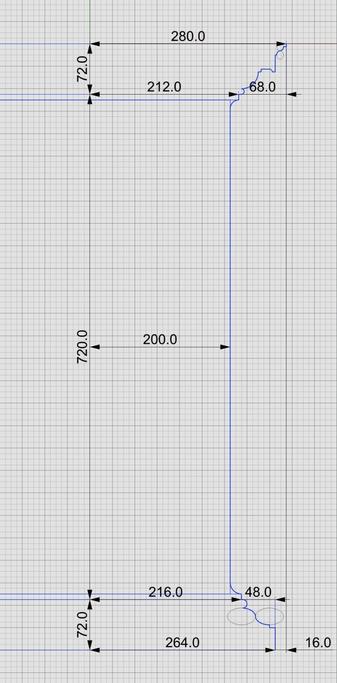
Classic #IonicScroll #Scaffolding Take the time to understand the measurements of this scaffolding plan in the broader context of the #IonicCapital measurements, as this is the bedrock on which the #scroll reconstruction rests. First, note that there are 5 rectangles labeled M, N, P, Q, and R, where M and N are coplanar with the large #volute at the front of the scroll. P and Q are congruent, with P exactly midway between the front and the back of the scroll, and Q exactly 3/4 of the way from front, or 1/4 from back. R is the smallest of them and lies at the back of the bell-shaped part of the scroll, but ahead of the ribbon bearing the 3-strand #braid. M completely encloses the volute, including #ArcZero, but much of Arc zero is discarded later. So, the part of the volute that really matters is enclosed by N, whose width is 112 units, height the same as M at 128 units, and the width of M itself is exactly µ or 144 units. So these measurements are in the ratio 7:8:9. The width of P and Q is 56 units, which is exactly half the width of N. Recall from the post on #IonicCapital #Tectonic Surfaces [https://pixelfed.social/p/Splines/792124787573855518] that the unadorned capital is also exactly 112 units, divided into two halves of 56 units each. R is concentric with P and Q and its width is exactly half of the width of P and Q, which are exactly half the width of N. Top of R is 32 units from top of N and 16 units from top of P and Q. Bottom of P and Q are 32 units from bottom of N and 16 units from bottom of R. Finally note the diagonal line from the origin to the #eye with a point in the middle. That middle point is the center of rectangle labeled N. It shows that the volute #eye, the center of N and the centers of concentric rectangles P, Q, and R would be collinear if these rectangles were coplanar. All of these constraints point to warrantable consistency and coherence of the scaffolding measurements, justifying their use in scroll reconstruction.