#EggsAndDarts is a common classical design motif with endless variations, two of which are shown here — the top-left variant has convex eggs and the bottom-left variant has concave eggs. The sketch on the right shows the bottom view of the concave variant.

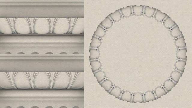
This motif is neither specific to the #IonicOrder, nor limited to the #ovolo of the capital. It is common to find it laid on linear #moldings like #cymaRecta or #cymaReversa of a #cornice.

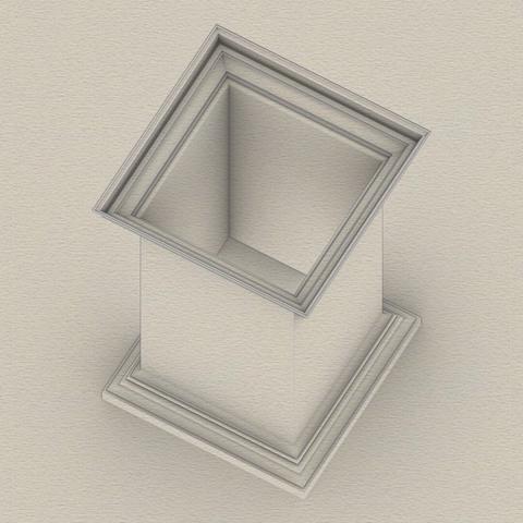
The egg shape, the dart shape, the degree of convexity or concavity, and so on, are infinitely variable from subtle to pronounced. Designers are not limited to convex or concave, and it is possible to combine both in a single design. Also, it is not necessary to use the eggs and dart motif at all. There are infinite possibilities. However, when the eggs and darts motif is used, it is almost invariably sliced off at the top, as the bottom view of concave variant on the right reveals.

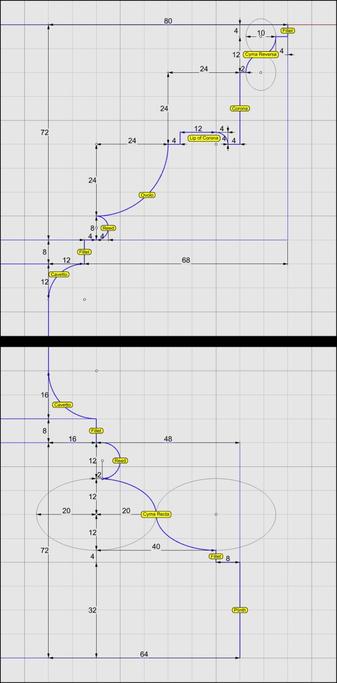
The concave version here is quite subtle, but a more pronounced version can be really eye-popping. I will show how to construct one using just straight lines and circular/elliptical arcs exclusively as I originally promised in https://pixelfed.social/p/Splines/789956327130679640.

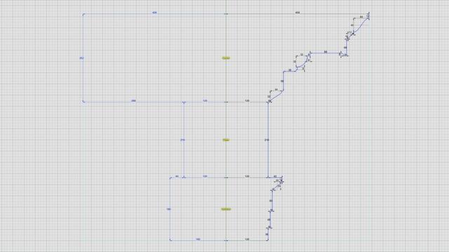
As usual, we start with a flat 2-dimensional plan with lines and ovals to use as #sweepingRails. Then, we add circles and arcs as #sweepingCurves to define the cross-sections. After sweeping the cross section curves on the rails, we create the eggs.

Simply #revolve an ellipse on its major axis to get the convex version of an egg. To get the concave version of an egg, simply create a flat slab and perform a #booleanDifference on that slab using a convex egg.

Once we have all of this preparatory work done, we have to transfer the 3-dimensional design from the flat surface it was originally created on to the #doublyCurved surface of the Ovolo. This requires some elementary calculations using circle geometry.

Previous— https://pixelfed.social/p/Splines/795361973789834465
Splines (@Splines@pixelfed.social)

This sweeping shape is a timeless design that first appeared in the scrolls of the #IonicCapital as the most distinctive part of the #IonicOrder in classical Greco-Roman architecture more than 2500 years ago. Shown here with a zebra pattern on the wireframe of a CAD model to accentuate its features and attest to the smoothness of its 3-dimensional surface, the design has been refined many times since the original version over the last two millennia. The two most remarkable things about this design are that: — It can be recreated with modern CAD tools by drawing simple 2-dimensional straight lines and circular arcs exclusively. The end result is truly breathtaking and makes one wonder how architects visualized the result and put theory into practice. In the CAD model, the ultimate surface is a #NURBS surface that uses #BSplines extensively, but none of the B-splines or surfaces need to be created "by hand." One only has to draw straight lines and circular arcs with accurate measurements snapped to grids. — For a design that has survived the ages, it is lamentable how few authoritative sources that accurately describe fine details and exact reconstruction methodology remain accessible to the general public in the age of Internet. The most comprehensive is the 10-volume tome that Marcus #Vitruvius Pollio, a Roman architect and engineer, wrote for #JuliusCaesar and his successor Emperor #CaesarAugustus. [https://www.gutenberg.org/files/20239/20239-h/20239-h.htm] I frequently use two more authoritative sources: — "Regola delli cinque ordini d' architettura," or simply #RegolaArchitettura by Giacomo Barozzi da #Vignola [https://archive.org/details/gri_33125008229458/page/n3/mode/2up], and — "A Course in Theoretical and Practical Architecture," or simply #PracticalArchitecture by Francisco Salvatore #Scarlata (#Bordonaro), which documents #VignolaProportions in tabular form [https://babel.hathitrust.org/cgi/pt?id=mdp.39015031201190&view=1up&seq=5]

Pixelfed
Classic variation of the #IonicEntablature. Left side shows the macro-level plan. Right side shows the detailed plan for the #moldings.

All moldings should be familiar from the #IonicPedestal, except the #fascia — flat bands, of which there are 3, at the bottom of the #Architrave. The fascias grow progressively taller, starting at 36 units at the bottom, to 48 in the middle, and 60 at the top, with each successive one offset horizontally by 6 units from the previous one.

Above the fascia, we have a #cymaReversa which is 24 units tall and 20 units wide. Here we are using half turn of a helix with a vertical axis. Either helix or elliptical arcs are acceptable, but the choice must be consistent across the entire order. You cannot use ellipses in the pedestal and helices in the entablature, for example.

If you do use a helix, remember that it is a 3D shape like a round coil. To use it as a #profileCurve, it must be flattened to a 2D shape by #projecting it to the #constructionPlane. I will describe this technique in detail later.

The #frieze is a flat surface with no moldings. It is meant as a blank space on which to put custom decorative 3D #ReliefCarvings or sculptures.

There are no new moldings in the #cornice. Note that the order of #cymaRecta and cyma reversa are reversed from that of the #pedestal, with cyma recta at the top and cyma reversa at the bottom. The only difference between the two is that the recta has a horizontal axis and reversa has a vertical axis. Rotating either one 90° yields the other.

So, the bottom of the cornice starts with a cyma reversa 32 units tall and 34 wide. This is followed by a fascia 56 units tall on which the #dentils will appear later on. The 36 unit horizontal offset for the 4-unit thick fillet above it is to leave room for the dentils.

This is followed by a #reed (8 units), #ovolo (32 units), #corona (48 units), cyma reversa (16 x 12 units), fillet (4 units), cyma recta (40 x 44 units), and fillet 12 units
From https://pixelfed.social/p/Splines/790645054230337543, we now have an open surface for the #IonicPedestal. To finish this, close the #planarHoles at the top and bottom with flat caps and join everything. And just like that, we have finished 1/3 of the complete #IonicOrder with very little work.

To ensure that your finished object is amenable to #3DPrinting or #CNCMilling, always check the edges of your object after all surfaces have been joined. Do this EVERY time you join surfaces to create a closed object.

Most CAD programs will offer edge analysis tools that let you detect #nakedEdges or #nonManifoldEdges. If you have either of those, your object is not #airtight, and you will not be able to physically realize it.

This version of the pedestal uses the classic variation of #CymaRecta and #CymaReversa. If you want to remain faithful to the original, then you are done.

However, designs are rarely static and they continue to evolve. There is an opportunity for a slight refinement at the top and bottom of the pedestal without compromising the integrity of the order, but it requires the introduction of a new kind of curve — a #helix, which is a coil-shaped 3D curve.

I will discuss the #helixVariation later. For now, look closely at the #basement and notice how pronounced the turns of the cyma recta are. Instead of using elliptical arcs in the #primaryProfileCurves of the cyma recta and cyma reversa, it is possible to substitute a half-turn of a helix that has been flattened to a 2D shape. The result is a softer, more gradual profile curve that produces a very refined shape.
Splines (@Splines@pixelfed.social)

If you've been longing for some 3D adventure, your wait is over. We have here some of the most basic 3D operations that you will use over and over. First #join all #primaryProfileCurves into a single curve that has both straight lines and arcs. If you are unable to join them, look closely at the bottom #fillet of the #dado where it meets the top of the #reed of the #basement. There is a gap of 2 units between the fillet and the arc of the reed. Close the gap with a straight line and join the curves. Switch from the front view to the right view, and #extrude the joined profile curves on both sides of the profile curve so that the full extrusion is a little over the total width of the pedestal. A good rule of thumb is to extrude at least 1/8th extra on both sides of the joined profile curve. This extrusion is shown in the attached image as the gray surface in perspective view. Switch back to the front view and centered on the #columnAxis, draw a rectangle that is somewhat taller than the total pedestal height so that it extends past both the top and bottom of the pedestal extrusion from the previous step. The total width of this rectangle should be about 1.5 times the width of the pedestal. This is because we will create a cutting surface with this rectangle and rotate it 45° in the top view, and then rotate a copy of that another 90°, as shown by the flat red surfaces. The reason the width must be approximately 1.5 times (or larger) is because #Pythagoras told us that the hypotenuse of a unit square is 1.414 units. So 1.5 times should be enough. Use the two cutting planes to cut, split, or trim the extruded surface (depending on the terminology of your CAD program). This is called #mitering. Discard the excess of the extruded surface from both ends. Also discard or hide the red mitering surfaces. Switch to the top view and rotate the #mitered extrusion repeatedly at 90° about the column axis until you have all four sides, and join them all into a hollow shape.

Pixelfed
This shows the detailed measurements of the top and bottom portions of the #IonicPedestal. For macro-level measurements, see https://pixelfed.social/p/Splines/790571135473463588

Each of the blue curve segments (lines and arcs) that are marked with a yellow bubble is the #profileCurve for a #molding whose name is inside the bubble.

Starting at the bottom, we have a #plinth, a #fillet, a #cymaRecta, and a #reed as part of the #basement of an Ionic pedestal.

Next up, we have a #fillet and a #cavetto at the bottom of the #dado, and another cavetto and fillet at the top of the dado.

Moving higher up, a reed, an #ovolo, a #corona, a #cymaReversa, and a final fillet top off the cap of the pedestal.

They are called profile curves because each is the outline or silhouette of a 3D molding as seen from one side or in a cross section. In the case of a pedestal, these curves can be used directly to recreate the 3D shape of the pedestal. For this reason and in this case, I call them #primaryProfileCurves.

This is not always the case. For more complex shapes, such as the #scroll surface of an #IonicCapital shown in https://pixelfed.social/p/Splines/789956327130679640, the profile curves recovered by #reverseEngineering the image scans in #Vignola's book cannot be used directly to sweep the scroll surface because the scroll shape is not cylindrical. Like the inside of a rose, the scroll surface follows the outlines of spiral #volutes in the front and back, neither of which are circular. So, additional steps are necessary to derive the curves that we can actually use to reconstruct the surface.

In the case of the scroll surface, the derivation of these curves is not trivial and not obvious, but it is not difficult to understand, and no math is involved. There are multiple sets of curves, and each successive set is derived from a previous set. I call them secondary, tertiary, and quaternary curves.

For now, we stick with the primary profile curves for the pedestal.
Splines (@Splines@pixelfed.social)

This shows macro-level measurements for the #IonicPedestal. The key to #effectiveModeling is to simplify a complex shape into elementary components. Sometimes, this involves mentally flattening and reducing 3D shapes to 2D shapes, extracting elementary curves from them, and then recreating the 3D shapes from the extracted 2D curves. This is not always easy for organic shapes (which can still be approximated by Bézier curves). I extracted the #primaryCurves for the #IonicScroll surface in https://pixelfed.social/p/Splines/789956327130679640 after a lengthy trial-and-error process that involved #curveFitting images from #Vignola’s book, #RegolaArchitettura. I had to reverse engineer the details because the measurements have either been lost, or are locked away in some library. Web search yields no details on these measurements. Fortunately, for geometrical shapes like pedestals, this is very easy. Because of its square footprint, mentally slicing it through the middle from top to bottom, it is easy to “see” the outline. Another way to think about #curveExtraction is to shine an imaginary bright light on an object from behind in a dark room to reveal its silhouette. For the pedestal, even this silhouette or outline can be further reduced because the shape is symmetrical about the #columnAxis. With this realization, we only need to focus on one half of the outline, and methodically proceed from bottom to top, marking every kink and inflection point on the outline. Fortunately, the other authoritative book, #Scarlata’s #PracticalArchitecture, I mentioned in my introductory post already documents #VignolaProportions in tabular form. So we can skip everything else and go directly to that. Total height of #IonicPedestal is 864 units (108 parts, or 6*µ) of which the #PedestalBasement and #PedestalCap are each 72 units (9 parts, or µ/2) and the #Dado is 720 units (90 parts, or µ*5) tall.

Pixelfed

⬆️ #IonicPedestal #3DModeling #ProfileCurves

Bottom-right portion of profile curves for #Ionic Pedestal without dimensions, but still showing the centers for all arcs.

Notice that the center for the #reed is 2 units to the right of the center for the top arc of #CymaRecta.

The two gaps to the left of the reed MUST be closed if you want your models to be airtight for #3DPrinting. If you forget, the model might render fine but the model will have #nakedEdges.

⬆️ #IonicPedestal #3DModeling #ProfileCurves

Bottom-right portion of profile curves for Ionic Pedestal. Details in Alt text.

Starting from bottom, the #plinth, #fillet, #CymaRecta, and #reed belong to the #Basement.

The fillet and #cavetto (circular arc) above those belong to the #Dado.

The cyma recta is 40 units wide and 24 tall. So the arcs for that are cut from ellipses.

A refined variation of cyma recta uses half turn of a helix instead of 2 elliptical arcs and will be presented later.