To ensure that your finished object is amenable to #3DPrinting or #CNCMilling, always check the edges of your object after all surfaces have been joined. Do this EVERY time you join surfaces to create a closed object.
Most CAD programs will offer edge analysis tools that let you detect #nakedEdges or #nonManifoldEdges. If you have either of those, your object is not #airtight, and you will not be able to physically realize it.
This version of the pedestal uses the classic variation of #CymaRecta and #CymaReversa. If you want to remain faithful to the original, then you are done.
However, designs are rarely static and they continue to evolve. There is an opportunity for a slight refinement at the top and bottom of the pedestal without compromising the integrity of the order, but it requires the introduction of a new kind of curve — a #helix, which is a coil-shaped 3D curve.
I will discuss the #helixVariation later. For now, look closely at the #basement and notice how pronounced the turns of the cyma recta are. Instead of using elliptical arcs in the #primaryProfileCurves of the cyma recta and cyma reversa, it is possible to substitute a half-turn of a helix that has been flattened to a 2D shape. The result is a softer, more gradual profile curve that produces a very refined shape.

Splines (@[email protected])
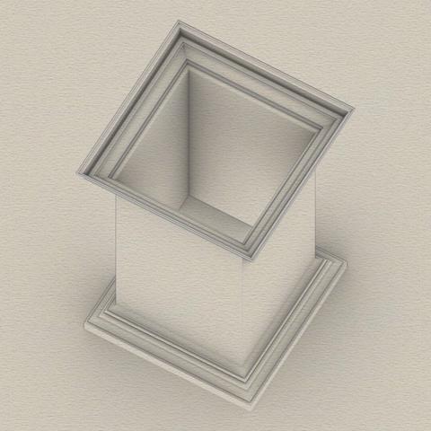
If you've been longing for some 3D adventure, your wait is over. We have here some of the most basic 3D operations that you will use over and over. First #join all #primaryProfileCurves into a single curve that has both straight lines and arcs. If you are unable to join them, look closely at the bottom #fillet of the #dado where it meets the top of the #reed of the #basement. There is a gap of 2 units between the fillet and the arc of the reed. Close the gap with a straight line and join the curves. Switch from the front view to the right view, and #extrude the joined profile curves on both sides of the profile curve so that the full extrusion is a little over the total width of the pedestal. A good rule of thumb is to extrude at least 1/8th extra on both sides of the joined profile curve. This extrusion is shown in the attached image as the gray surface in perspective view. Switch back to the front view and centered on the #columnAxis, draw a rectangle that is somewhat taller than the total pedestal height so that it extends past both the top and bottom of the pedestal extrusion from the previous step. The total width of this rectangle should be about 1.5 times the width of the pedestal. This is because we will create a cutting surface with this rectangle and rotate it 45° in the top view, and then rotate a copy of that another 90°, as shown by the flat red surfaces. The reason the width must be approximately 1.5 times (or larger) is because #Pythagoras told us that the hypotenuse of a unit square is 1.414 units. So 1.5 times should be enough. Use the two cutting planes to cut, split, or trim the extruded surface (depending on the terminology of your CAD program). This is called #mitering. Discard the excess of the extruded surface from both ends. Also discard or hide the red mitering surfaces. Switch to the top view and rotate the #mitered extrusion repeatedly at 90° about the column axis until you have all four sides, and join them all into a hollow shape.