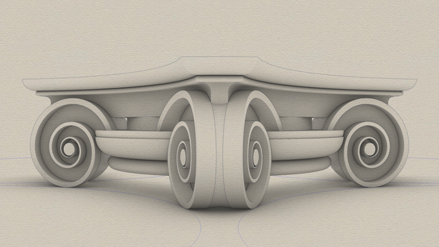
#ModernIonicCapital sketch
The modern
#IonicCapital with curved faces and radial symmetry is a drop-in replacement for the classic Ionic capital with flat faces.
Unlike the classic variant, which has a rectangular footprint, the modern variant has a footprint that fits in a square. In the classic variant, the volutes and scrolls project out so that they are visible from the top. In the modern variant, there are no scrolls, the volutes have a curved face, and they are completely nestled under the top.
The sketch omits the
#fillet at the bottom because we added that to the column
#shaft in
https://pixelfed.social/p/Splines/791794072490907090.
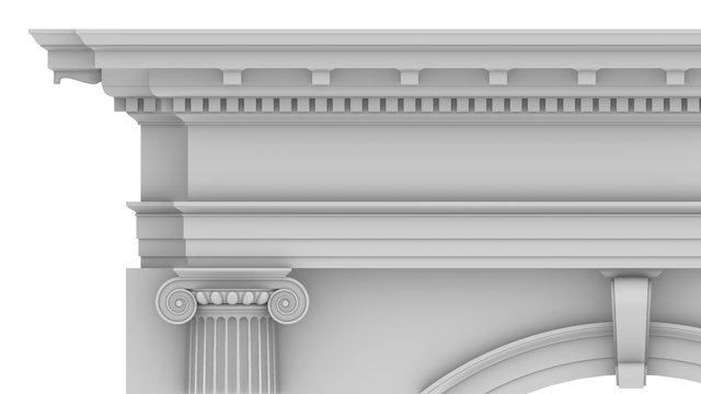
So, we start at the bottom with an
#astragal which is exactly the same size as in the classic variant.
Next up from the bottom is the
#ovolo which is shorter than in the classic variant. It still has a
#tectonicSurface on which
#decorativeElements rest, and a
#virtualSurface that envelops the decorative elements. In this case, I chose a minimalist design with no
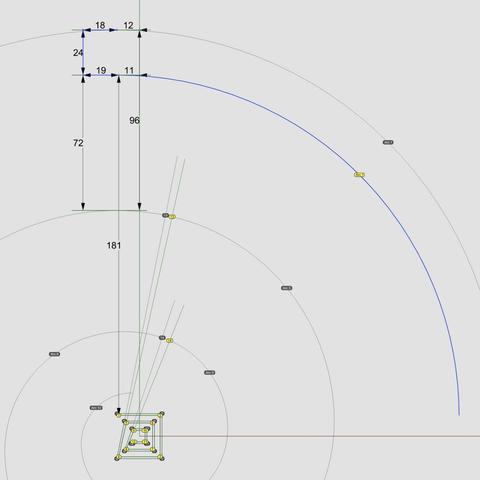
#eggsAndDarts. Instead, I use another plain ovolo as a substitute that is offset from the tectonic surface by 1 part (or 8 units, when µ = 144).
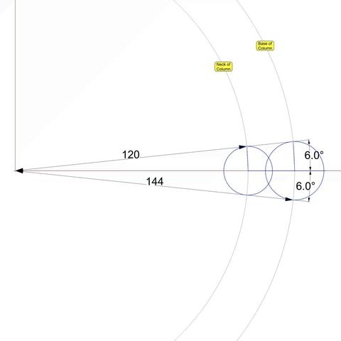
Above the ovolo is the
#channel, which in this case is a round slab whose surface matches the neck of the column with a radius equal to 5/6 of µ (120 units).
Above the channel is the
#abacus which has a curved face that is repeated on all four sides. There is an abacus with flat sides in the classic variant as well, but it is not visible from the front because it is hidden behind the
#volute slab. In fact, the vertical
#braidsAssembly in the classic variant is attached to the abacus.
Above the abacus is a
#reed, and above that, another small Ovolo that tops the modern capital.
The curved volutes follow the blue circular arcs at the bottom of the sketch. The volutes are shaped like a wedge, as can be seen more clearly in the corner facing the front. The portion of the wedge between the outer rims has a concave surface.