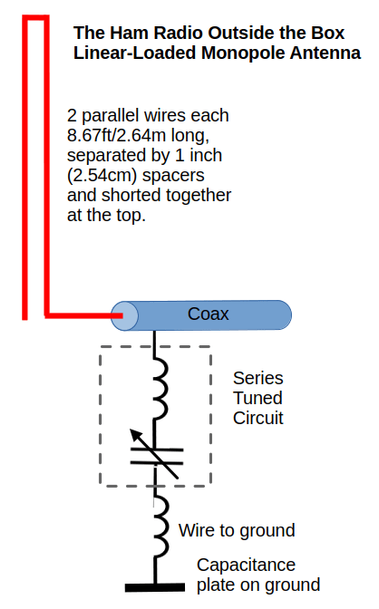
A Linear-Loaded Monopole antenna for hiking
There is a lot of information online about Linear-Loaded Dipoles, but I haven’t found anything at all about cutting a Linear-Loaded Dipole in half to create a Linear-Loaded Monopole worked against ground. The legendary L.B. Cebik (W4RNL, SK) published a design philosophy for an 80m Linear-Loaded Monopole, but it didn’t match what I had in mind. So I decided to build one for the purpose of experimentation. Maybe I could make it into a compact, lightweight antenna capable of rapid deployment while hiking – maybe.
What is Linear-Loading?
According to my search engine’s “Search Assist”, “Linear loading is a technique used in antenna design where a portion of the antenna wire is folded back on itself to reduce its overall length while maintaining good electrical performance. This method allows for a shorter antenna that can still operate effectively on the desired frequency.”
Sounds very simple doesn’t it? In the real world, where the RF hits the ether, it gets a little more complicated – especially when venturing outside the box. I could have made life nice and simple by building a Linear-Loaded Dipole; there are lots of designs available online that I could have used. But a dipole is too large for agile, rapid deployments; it needs a taller pole which, in turn, requires pegging into the ground and guy wires. I could use a tree limb for support, but only if suitable trees are available; often they are not. No, my requirement for a very simple hiking antenna implies a vertical antenna – a short vertical antenna.
Short antennas are easy to build; simply add a loading coil at the base and Bob’s your uncle. But that won’t qualify for my purposes. Short loaded antennas have a reduced radiation resistance and ohmic loss in the coil – they are inefficient. So how to shorten an antenna while maintaining efficiency? That’s where linear loading comes into play. A linear-loaded antenna is almost as efficient as a regular version.
How to build a Linear-Loaded Monopole?
It should have been “EZ-PZ”. Just take the dimensions from any of the online designs for a Linear-Loaded Dipole and cut them in half. That’s where I started. For a 20 meter antenna, a length of around 11 feet of window line, shorted at one end, is a good starting point. I hauled it up the mast in my newly glacier-free backyard, attached a counterpoise wire and started trimming. Between snips the resonant frequency was monitored on my RigExpert antenna analyzer. I use the term “resonant frequency” loosely in this context. The expected impedance of a quarter-wave vertical is around 37 ohms which implies there will be some reactive component to the impedance. I searched for a dip in SWR over a wide frequency range until it was possible to locate where the antenna was “resonant”.
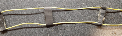
Home made ladder line. The separators are made of shrink wrap heated with a Weller soldering gun with plastic welding tip. Lots of work and not very elegant, but practical and cheap!
So long John?
A low SWR in the region of the bottom end of the 20 meter band was the target, but the dip in the curve was below the bottom of the band – way below. I snipped and snipped until that dip fell where it was needed. Then the counterpoise length was adjusted until the lowest SWR was obtained. How long was my ladder line? A large pile of snipped ladder line lay on the grass beneath the pole. When I took the antenna down, laid it out on the ground and measured its length it was quite a surprise to see the ladder line radiator was only 8.67ft (2.64m) long. And the counterpoise length was 18ft (5.5m).
Jingo-la-ba!
Will it QSO? I fired a smidgen less than five watts into it and received a response from a station somewhere in the US with an encouraging signal report. Well, at least it “works”. But now came the next step. That pesky 18ft counterpoise had to go, to be replaced with the 2T2C (Tuned Tank Circuit Coupler) described in the last post.
A new challenge
The 2T2C ground coupler was directly connected to the ground side of the short coax feedline and a further wire was added to connect to a small capacitance plate on the ground. Life is complicated and then you die, so why do I insist on adding more complications? It’s called experimentation – experiment and learn! I learned. I learned that my choice of inductance and capacitance for the 2T2C resulted in impossibly sharp tuning of the ground circuit. The 2T2C needed a design modification to reduce the inductance and increase the capacitance. Spreadsheet modeling suggested this would make the 2T2C easier to adjust. I needed to confirm that before rebuilding the 2T2C, but how?
L-match innovation
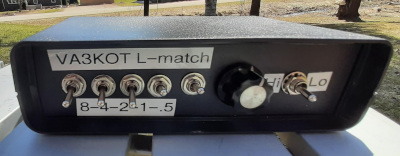
The answer came in the form of a variable L-match that I built quite recently. It has switch selectable inductors and a variable capacitor. It could be adapted to fit this bill very nicely.
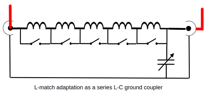
This idea was inspired by VK3YE who published a YouTube video about it some time ago. At one terminal of the L-match a connection is made to the BNC center conductor. At the other terminal, a connection is made to the shield side of the BNC. If you trace the signal path through the device it can be seen that the inductors and capacitor are in series. Now we have a Ground Tuning Unit (GTU) and can use binary selection of the inductances, together with rotating the variable capacitor, to determine the combination of inductance and capacitance for easiest tuning of the ground connection.
The inductances available on my L-match are 0.5, 1, 2, 4, 8 microhenries, allowing the inductance to be varied up to 15.5 microhenries in 0.5 microhenry increments. The variable capacitor is a 30-160pF polyvaricon.
Now, with the 8.67ft linear-loaded vertical erected and the “L-match GTU” making the ground connection via a capacitance plate on the ground, it was easy to select values that would allow smooth adjustment of the antenna SWR. It was found that 1 or 1.5 microhenries worked best. With these values selected the polyvaricon could be adjusted around mid-range to easily select best SWR.
A caution!
There’s a gotcha with this technique. My L-match has a switch to connect the top end of the variable capacitor to either the input or output. This is used to enable fast selection of either high or low impedance antennas. Referring to the diagram above, if the switch (not shown) is set to connect the variable capacitor to the left side of the inductors, this technique will not work. The inductors will be out of circuit and only the variable capacitor will be in circuit.
Will it still QSO?
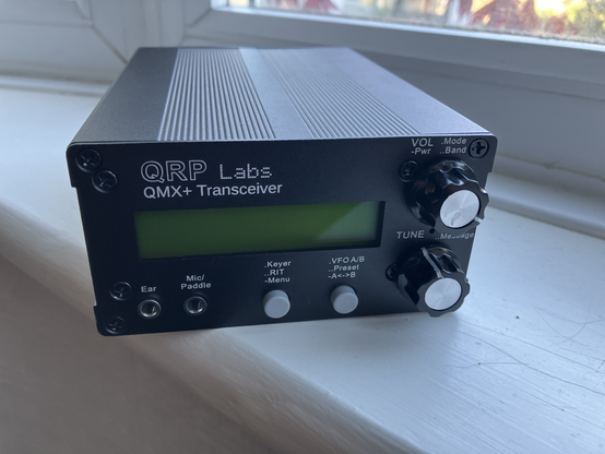
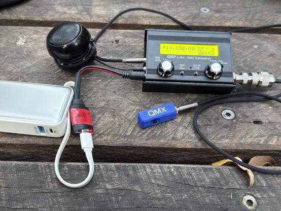
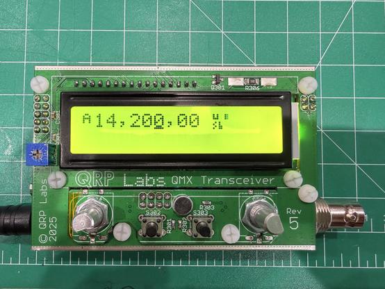
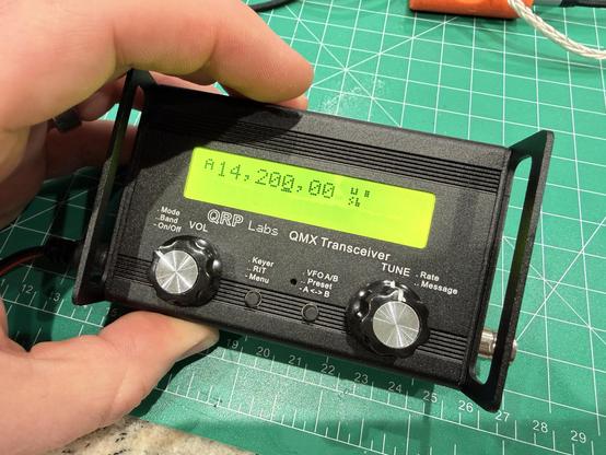
My low-band QMX was dug out of its field pack and hooked up to the revised antenna (8.67ft of vertical window line with the “L-match GTU” providing the “other half” of the antenna. Using the “Tune SWR” feature of the QMX, the best SWR of 1.36:1 was obtained by a very small adjustment of the variable capacitor in the L-match GTU. Then it was time to go hunting. My best contact was in the state of Arizona (the “Arid Zone”?) almost 3000km away from my station in Southern Ontario. Signal reports were 599 each way. My sent report was a genuine 599 suggesting the antenna has good ears. The 599 report I received may have been genuine or perhaps it was just a “contest report”. In any event a good solid contact was made. A second contact into North Carolina only yielded a 549 signal report, but perhaps the low angle radiation pattern favored longer distance contacts.
Notice that the L-match GTU has no RF current meter. I could perhaps have inserted my home brewed RF current meter in circuit, but it wasn’t really necessary. Adjusting the ground current also regulates the radiating element current. Simply adjusting for lowest SWR indication on the radio peaks the radiated energy.
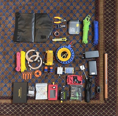
For practical outdoor use while hiking through the woods and rapidly deploying the antenna in clearings, the L-match GTU will be replaced with a much smaller series L-C coupler (2T2C). A 13ft Crappie pole is used to support the antenna. It collapses to the perfect length for carrying inside a fishing pole bag (no surprise there then) and is very lightweight.
There’s another gotcha
When the current distribution on the antenna was viewed in EZNEC it was discovered that the current maximum is in the ground circuit instead of in the radiator. Just like any ground-mounted antenna, this can lead to ground losses and inefficiency. However, the primary design objective was not to seek a Nobel Prize in antenna physics, but to come up with a design that meets the objective of a rapid deployment, simple antenna for hiking through the woods. The Linear-Loaded Monopole may just meet that requirement, but I have other ideas to try first. Stay tuned.
Help support HamRadioOutsidetheBox
No “tip-jar”, “buy me a coffee”, Patreon, or Amazon links here. I enjoy my hobby and I enjoy writing about it. If you would like to support this blog please follow/subscribe using the link at the bottom of my home page, or like, comment (links at the bottom of each post), repost or share links to my posts on social media. If you would like to email me directly you will find my email address on my QRZ.com page. Thank you!
The following copyright notice applies to all content on this blog.
This work is licensed under a Creative Commons Attribution-NonCommercial-NoDerivatives 4.0 International License.
#AmateurRadio #Antennas #Counterpoise #Ground #OutdoorOps #Portable #QMX