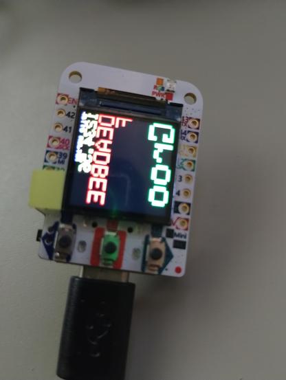
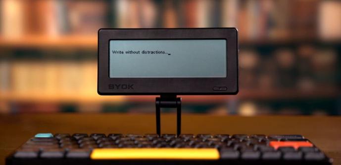
BYOK is a pocket-sized distraction-free writing device (but you’ll need to bring your own keyboard)

While it’s easy enough to sit down at a computer and open up a word processor to start writing, it’s also extraordinarily easy to get distracted by all the other things your PC (or tablet, or phone) can do. So in recent years we’ve seen a growing number of distraction-free writing devices that offer a minimalist feature set designed to help you focus on putting your thoughts down in words, […]

#bringYourOwnKeyboard #byok #crowdfunding #distractionFreeWriting #esp32 #esp32S3

Read more: https://liliputing.com/byok-is-a-pocket-sized-distraction-free-writing-device-but-youll-need-to-bring-your-own-keyboard/

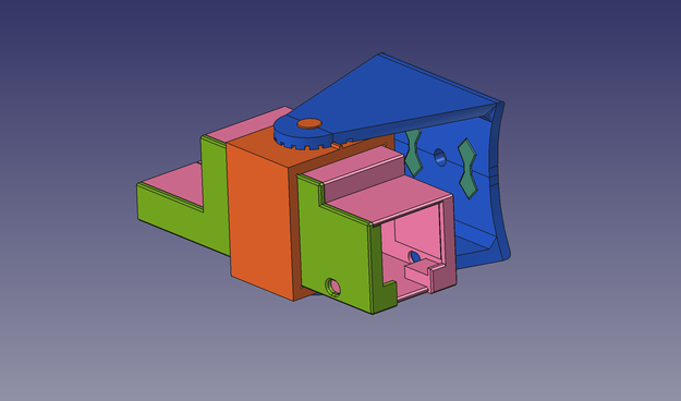
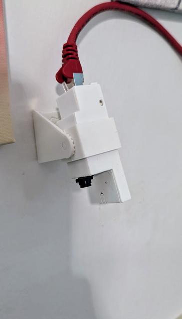
I improved my #esp32s3 LAN enclosure and also made a wall-mount for it with adjustable angle.

https://www.printables.com/model/1327421

It's main purpose ist actually being a #homeassistant BLE proxy, but since the camera was already there, I am also using it to monitor my 3D printer.

#freecad
#creathing
#3dcrafting
#3dmodeling
#3dmodel
#waveshare

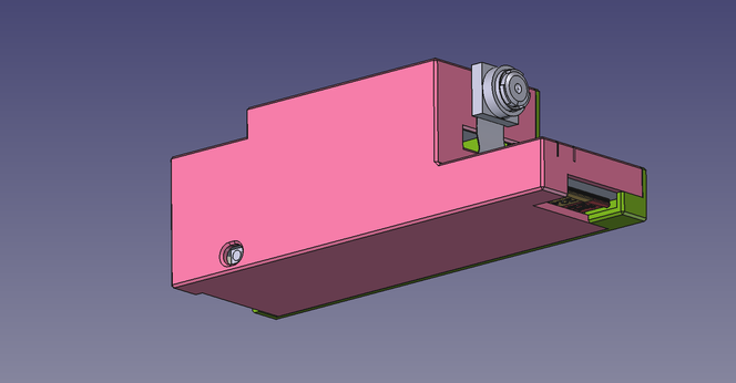
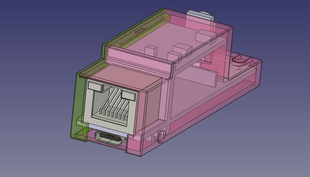
Need an enclosure for an ESP32-S3-ETH module with OV2640 CAM and POE module?

I made a simple one, since I could not fine one. 😉

https://www.printables.com/model/1326077

boost if you like
msg if you have a suggestion for a version with GPIO access.

#freecad #creathing #3dcrafting #3dmodeling #3dmodel #esp32s3 #waveshare #poe

Ei, he invertit un parell d'hores en un altre projecte en plan "em baixo aquest Firmware amb tot fet i el flasheijo en aquest catxarro petit", i flipo amb com funciona. Un assistent tipus Alexa, amb quasi tot offline, en un #ESP32S3 del tamany d'un rellotge Smart d'aquests.

I jo programant el mateix en Python en una RPi.

Estic al·lucinant.

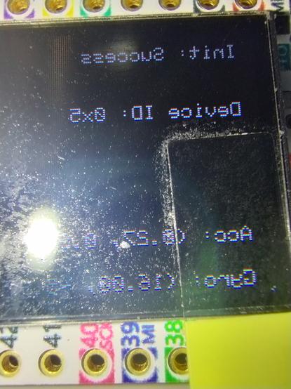
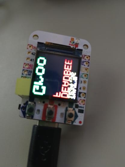
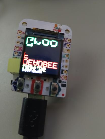
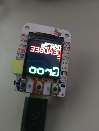
Here is another sketch running, turns out the font not upside down, just flipped and I'm starting to wonder if it is a weird quarky display panel - like the panel is backward, and it's not really a problem of the library.

Thou, Adruino_GFX library seems to be fine using this display.... maybe I should just use that library.

#Arduino #ESP32S3 #ArduinoGFX #Adafruit

This is a Wemos ESP32-S3 pro mini board, it has a 0.85" 128x128 #GC9A01 LCD, and I'm using an #Adafruit Library - which seems to work very well - except when it comes to displaying text.....
It's like the #font is render flipped and upside down, has anyone seen this before - how would you go about fixing it?

#ESP32S3

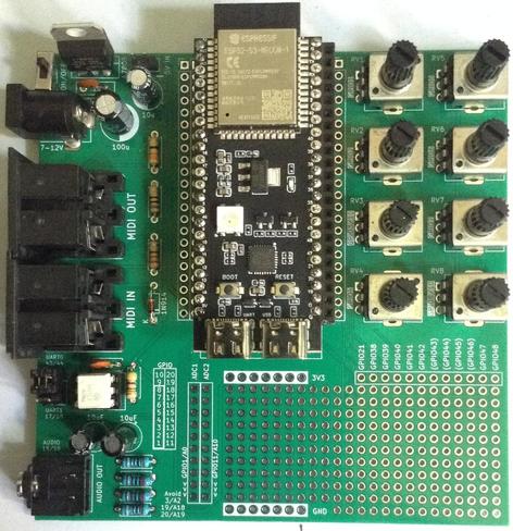
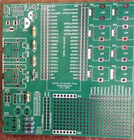
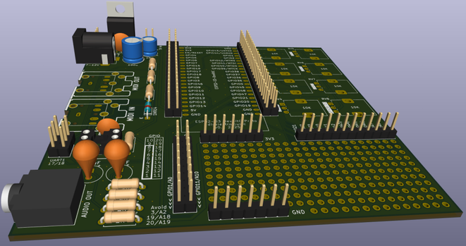
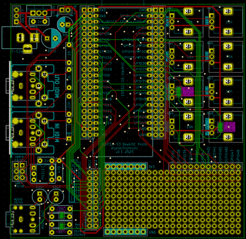
An ESP32-S3 DevKitC prototyping board with MIDI, PWM audio output, potentiometers and its own power circuit.

https://diyelectromusic.com/2025/05/25/esp32-s3-devkit-experimenter-pcb-design/

#ESP32S3 #MIDI #SynthDIY

ESP32 S3 DevKit Experimenter PCB Build Guide

Here are the build notes for my ESP32 S3 DevKit Experimenter PCB Design.

Warning! I strongly recommend using old or second hand equipment for your experiments.  I am not responsible for any damage to expensive instruments!

If you are new to electronics and microcontrollers, see the Getting Started pages.

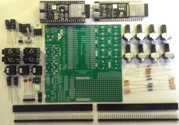
Bill of Materials

  • ESP32S3 DevKit Experimenter PCB (GitHub link below)
  • ESP32S2 DevKitC (official or clone – see ESP32 S3 DevKit)
  • MIDI Circuit:
    • 1x H11L1 optoisolator
    • 1x 1N4148 or 1N914 signal diode
    • Resistors: 1x 10Ω, 1x 33Ω, 1x 220Ω, 1×470Ω
    • 1x 100nF capacitor
    • Either: 2x MIDI DIN sockets (see photos and PCB for footprint)
    • Or: 2x 3.5mm stereo TRS sockets (see photos and PCB for footprint)
    • Pin headers and jumpers
    • Optional: 6-way DIP socket
  • Audio Output Circuit:
    • Resistors: 2x 1K, 2x 2K
    • 2x 10uF non-polar capacitors
    • 2x 33nF ceramic capacitors
    • 1x 3.5mm stereo TRS socket
  • Power Circuit:
    • 1x 7805 regulator
    • Electrolytic Capacitors: 1x 100uF, 1x 10uF
    • 1x 100nF Ceramic Capacitor
    • SPST switch with 2.54mm pitch connectors
    • 2-way header pins
    • 2.1mm barrel jack socket (see photos and PCB for footprint)
  • 8x 10K potentiometers (see photos and PCB for footprint)
  • Optional: 2x 22-way pin header sockets
  • Additional pin headers or sockets as required

Each circuit module is effectively optional. The position of the 22-way headers will depend on which type of module is used. The clone versions are 1 pin row wider than the official version.

There are some solder-bridge configuration options too, which will be discussed later.

Build Steps

Taking a typical “low to high” soldering approach, this is the suggested order of assembly:

  • All resistors and diode.
  • DIP socket (if used) and TRS socket(s).
  • Disc capacitors.
  • Switch
  • Jumper and pin headers.
  • 22-way pin sockets (if used).
  • Non-polar and electrolytic capacitors.
  • 7805 regulator.
  • Potentiometers.
  • DIN sockets.

Here are some build photos for the MIDI DIN version of the board. If using MIDI TRS sockets, then these can be installed at the same time as the audio socket.

If using 22-way headers for the DevKit, then the position will depend on which type of DevKit module is being used. In the photo below, I’ve installed 3 sets of 22-way headers to allow me to use either a clone or official module.

The remaining components can almost be installed in any order that makes sense at the time.

Once the main build is complete, two additional capacitors are required for the audio PWM output circuit. Two 33nF capacitors should be soldered across the 1K resistors. This is probably best done on the underside of the PCB as shown below.

Ignore the red patch wire. I managed to cut through a track whilst clipping the excess leads after soldering.

Configuration Options

The following are configurable and can be set by using pin headers and jumpers; solder bridges; or possibly wire links.

  • UART for MIDI – pin header + jumpers.
  • Audio Output – can be disconnected by breaking solder jumpers on rear of the board under 1K/2K resistors.
  • GPIO used for RV3 and RV8 – can be set using solder jumpers on rear of the board under RV3 and RV8.

Testing

I recommend performing the general tests described here: PCBs.

WARNING: The DevKit can be powered from either the USB sockets or the new power circuit, but not both at the same time.

The sample application section includes some simple sketches that can be used to test the functionality of the board.

PCB Errata

There are the following issues with this PCB:

  • I should have oriented the DevKit the other way up so that the USB sockets were on the edge of the board, not overhanging the prototyping area!
  • The Audio filter requires additional capacitors (see notes).

Enhancements:

  • None 

Find it on GitHub here.

Sample Applications

Analog Potentiometers

The following will read all 8 pots and echo the values to the serial monitor.

void setup() {
Serial.begin(115200);
}
void loop() {
for (int i=0; i<8; i++) {
int aval = analogRead(A0+i);
Serial.print(aval);
Serial.print("\t");
}
Serial.print("\n");
delay(100);
}

Audio PWM Output

The following will output a 440 Hz sine wave on the PWM channel on GPIO 15. Change to 16 to see the other one.

int pwm_pin = 15;#define NUM_SAMPLES 256uint8_t sinedata[NUM_SAMPLES];#define PWM_RESOLUTION 8#define PWM_FREQUENCY 48000#define TIMER_FREQ 10000000#define TIMER_RATE 305#define FREQ2INC(f) (f*2)uint16_t acc, inc;void ARDUINO_ISR_ATTR timerIsr (void) { acc += inc; ledcWrite (pwm_pin, sinedata[acc >> 8]);}hw_timer_t *timer = NULL;void setup () { ledcSetClockSource(LEDC_AUTO_CLK); for (int i=0; i<NUM_SAMPLES; i++) { sinedata[i] = 127 + (uint8_t) (127.0 * sin (((float)i * 2.0 * 3.14159) / (float)NUM_SAMPLES)); } timer = timerBegin(TIMER_FREQ); timerAttachInterrupt(timer, &timerIsr); timerAlarm(timer, TIMER_RATE, true, 0); ledcAttach(pwm_pin, PWM_FREQUENCY, PWM_RESOLUTION); inc = FREQ2INC(440);}void loop () { }

I’m getting a pretty good signal with a 33nF filter capacitor, but the signal still retails some bias. I’m getting a Vpp of around 1.1V.

But it starts out with a swing from around -200mV to +900mV. But this slowly improves over time and after a few minutes is much closer to a nominal -500mV to +600mV. I guess that is probably my cheap capacitors!

MIDI

Most of the MIDI monitors, routers and sending projects I have should work with the MIDI setup. In the default configuration, using UART0 (GPIO 43/44) for MIDI, that appears as Serial0 or the default MIDI configuration (more on serial ports on the ESP32S3 here: ESP32 S3 DevKit).

So the Simple MIDI Serial Monitor should just work and anything sent to the board should:

  • Illuminate the on-board (RGB) LED.
  • Echo back out to the MIDI OUT port.

Here is the full test code:

#include <MIDI.h>

MIDI_CREATE_DEFAULT_INSTANCE();

void setup() {
MIDI.begin(MIDI_CHANNEL_OMNI);
pinMode (LED_BUILTIN, OUTPUT);
}

void loop() {
if (MIDI.read()) {
if (MIDI.getType() == midi::NoteOn) {
digitalWrite (LED_BUILTIN, HIGH);
delay (100);
digitalWrite (LED_BUILTIN, LOW);
}
}
}

Note: as the MIDI is (probably) hanging of UART0 which is also routed to the USB “COM” port, it will be easier to upload via the USB “USB” port. This won’t clash with the MIDI circuitry on UART0.

Closing Thoughts

I seem to be having a run of “doh” moments with a few of these PCBs, but then that is the price I pay for taking shortcuts by only designing them in my head rather than prototyping them first!

But arguably, it is still a lot easier using a soldered PCB than attempting to build the various elements on solderless breadboard, so in a way that is what these prototypes are largely for.

So apart from the filter issue which is actually fairly easily solved, this seems to work pretty well.

Kevin

#define #ESP32s3 #include #midi #pcb #potentiometer #pwm

ESP32 S3 DevKit Experimenter PCB Design

This a version of the ESP32 WROOM Mozzi Experimenter PCB for the latest ESP32-S3 DevKitC board I’ve found.

For the background on the boards themselves, see my notes here: ESP32 S3 DevKit.

Warning! I strongly recommend using old or second hand equipment for your experiments.  I am not responsible for any damage to expensive instruments!

If you are new to Microcontrollers, see the Getting Started pages.

The Circuit

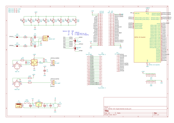
This is mostly just breaking out the pins of the ESP32S3 DevKitC to header pins, but there are a couple of additional features too:

  • There are additional rows of headers. The idea is to support the official and clone boards, which means coping with the fact the clone boards are 1 row of pins wider than the official boards.
  • There is MIDI IN and OUT with jumpers to select UART0 or UART1.
  • There is a stereo PWM output circuit (see notes below).
  • There are 8 potentiometers connected to ADC1.
  • There is a 7805 or equivalent regulator to provide power if required.

One slight complication is the possibility that GPIO3 (ADC1_CH2) is required as a STRAPPING pin or that GPIO8 (ADC1_CH7) is required for I2C (more in the previous post) so there is a solder bridge option for either of them to switch over to GPIO10 (ADC1_CH9) instead.

The complete GPIO usage is as follows:

GPIO0On board BOOT buttonGPIO 1-8Potentiometer 1-8GPIO 10Optional replacement for GPIO 3 or 8GPIO 15, 16PWM audio outputGPIO 43, 44MIDI if UART0 is selectedGPIO 17, 18MIDI if UART1 is selectedGPIO 1-20Analog breakout area*GPIO 21, 38-49Digital breakout area*GPIO 38 or 48Onboard RGB LED

* As already mentioned some of these have alternative or preferred functions.

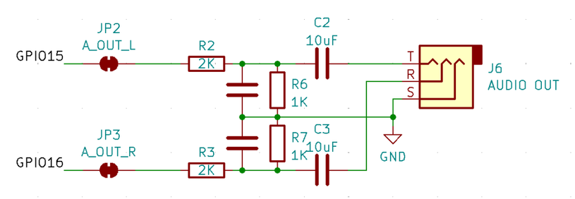
Audio PWM Output

I based this on the output circuit for my ESP32 WROOM Mozzi Experimenter PCB Design, but I was forgetting that the original ESP32 has a DAC and so only requires a potential divider to reduce the voltage levels and a capacitor to remove the DC bias.

The ESP32S3 does not have a DAC, so the output will have to be via PWM if no external DAC is added. This means this output circuit really needs a low-pass filter to smooth out the pulses from the PWM signal.

That hasn’t been included in the design, but can be implemented by adding capacitors across the terminals of the 1K resistors, as shown below.

Following the discussion from Arduino PWM Output Filter Circuit, we can see that a 2K/1K potential divider can (loosely) be treated as a ~666K resistor for the purposes of a low-pass filter calculation. So this gives me various options in terms of capacitor size as follows.

ResistorCapacitorRoll-off frequency666K10nF24 kHz666K33nF7 kHz666K68nF3.5 kHz666K100nF2.4 kHz

The greatest smoothing will come with the lowest cut-off, but 2.4kHz or 3.5kHz will limit the higher audio frequencies somewhat. But a 10nF might not give me enough smoothing.

It will also depend somewhat on the PWM frequency chosen. The higher, i.e. above the audio frequency range required, the better.

I’ll start with adding 33nF and see how that looks then might change with some experimentation.

If an external DAC is used, then there are solder jumpers provided that can be broken to disconnect this part of the circuit anyway.

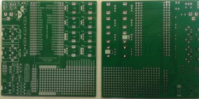
PCB Design

I initially considered only breaking out GPIO pins that weren’t being used for additional functions, but then decided I’d just break them all out alongside the prototyping area. Any pins that might be problematic or have an existing function on the board are labelled in brackets – e.g. (GPIO 43).

The solder jumpers for the GPIO/ADC choices are on the underside of the board.

As previously mentioned, the headers are arranged such that it will support the official DevKitC or the slightly wider clones.

The jumper for UART selection for MIDI can serve as a “disable MIDI to allow use of the serial port” function too if required.

There is also a twin jumper option for direct 5V input instead of going via the barrel jack and regulator.

Closing Thoughts

The omission of the capacitors in the PWM filter is a small annoyance, but it is relatively easily fixed.

Apart from that, there is a fair bit included on this board. It should serve as a good platform for further experimentation.

Kevin

#ESP32s3 #midi #pcb #potentiometer #pwm

ESP32 S3 DevKit

Having played a bit with ESP32-S3 now, in the of the Waveshare Zero format boards, I’d quite like to have a version of the ESP32 WROOM Mozzi Experimenter PCB for the latest ESP32-S3 DevKitC board I’ve found.

This is the introductory post that is my “notes to self” as I get to know the boards.

Warning! I strongly recommend using old or second hand equipment for your experiments.  I am not responsible for any damage to expensive instruments!

If you are new to Microcontrollers, see the Getting Started pages.

ESP32-S3 DevKitC Boards

There are a couple of ESP32-S3 official DevKits, in addition to the huge range of third party boards from the likes of Waveshare, Adafruit, and so on of course.

The main references for these boards are:

Note: although the C and M DevKits both have 44 pins and very similar functionality, the actual pinouts for the two boards are quite different. On the face of things, it looks like the pinout for the M version seems a bit more logical to me than the C version, but I’ve ended up with C boards, so that is what I’m going with! Much of what follows is applicable to both though.

It is also worth noting that I was looking at the ESP32-S3 as a possible replacement for the original ESP32 in my Educational DIY Synth Thing. But in terms of general features, the ESP32-S3 and ESP32 are actually pretty similar.

From the comparison here, here are some key features listed:

ESP32ESP32-S332-bit LX632-bit LX7single or dual coredual core240MHz (one variant at 160MHz)240MHz520KB SRAM512 KB SRAM448 KB ROM384 KB ROM0MB, 2MB, 4MB Internal Flash0MB, 8MB Internal FlashUp to 16MB External FlashUp to 1GB External FlashUp to 8MB External RAMUp to 1GB External RAM

Most of the peripherals are pretty similar too.

So the key difference is the switch from LX6 to LX7. As both support a single-precision floating point unit, and up to 240MHz operation in dual core modes, I’m not sure what the enhancement is at the moment.

One difference on Wikipedia is that the LX7 has “added instructions to accelerate machine learning applications” and it appears that there is a specific library that makes use of these instructions: ESP-DL. But I’ve not seen if any of this is likely to help me with audio.

I should also note that the original ESP32 is the only chip in the architectural family (as far as I can see) with an integrated DAC. There is certainly no DAC with the ESP32-S3.

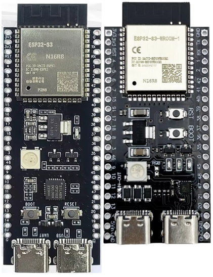
I was determined to go with the official ESP32-S3 DevKitC board this time. But on my first attempt I managed to end up with a very close clone! I have now have two variants as shown below. The original is on the left and the clone on the right.

The clones are very similar to the original but seem to have the following differences.

Physical Differences:

  • The clone is shorter and 2.54mm (i.e. a “pin row”) wider.
  • Buttons are in a different place.
  • USB-C ports in different place compared to the GPIO pins.

Electrical Differences:

  • The USB ports are swapped. The original has UART on the left, USB on the right. The clone is swapped.
  • Clone has a solder jumper on the rear for USB-OTG for the USB port. If soldered, this shorts a diode in the VBUS 5V line to allow the USB port to power an external device.
  • Original has an SK68xx LED (powered from 3V3), the clone has a WS2812 (powered from 5V), although they should be essentially the same code/protocol wise.
  • Original has the LED on GPIO38 (maybe – mine doesn’t). Clone has LED on GPIO48.
  • Clone has a solder jumper for the LED which is connected by default.
  • Original uses a CP2102N USB serial chip. Clone has a CH343P.
  • Original uses a SGM2212 regulator which has a 2.7-20V input range. Clone uses a CJ6107 with range 2.5-6V. Although in both cases the input is essentially 5V from USB VBUS.
  • The clone has an IN-OUT solder jumper. If soldered, this shorts a diode on header pin 21 (5V) to allow power to be fed into the board via the 5V pin.
  • The clone has a RX and TX LED.
  • The clone has the (strapping) pin 3 pulled HIGH to 3V with an additional 0R resistor in place in case that is not required.

Documentation for the original board: https://docs.espressif.com/projects/esp-dev-kits/en/latest/esp32s3/esp32-s3-devkitc-1/user_guide.html

Documentation for the clone: https://github.com/vcc-gnd/YD-ESP32-S3/tree/main/5-public-YD-ESP32-S3-Hardware%20info

At least the pinouts for the two modules seem the same, apart from the fact that one module is one-pin-header-row wider than the other.

ESP32-S3 DevKitC-1 GPIO Use

Strapping pins are used to set the configuration of the ESP32-S3 on power up. For details of the strapping pins and their use, see Section 4 in the ESP32-S3-WROOM-1 guide. The summary, and default settings for the ESP32-S3, is as follows:

GPIO0BOOT modeWeak pull-up to 1SPI bootGPIO3JTAG signal sourceFloatingEFUSE_STRAP_JTAG_SEL=0; GPIO3 ignored.
EFUSE_STRAP_JTAG_SEL=1; GPIO3=1 USB; GPIO3=0 JTAG pins.GPIO45VDD_SPI voltageWeak pull-down to 0GPIO46ROM message printingWeak pull-down to 0

Working through the datasheets, schematics and online guides, as far as I can make out the following GPIO pins all have an expected use on the DevKitC-1 boards, which can limit their use for general projects.

GPIOUse0, 3, 45, 46ESP32-S3 Strapping pins as described above.15, 16Optional: can be used to connect an external oscillator – not used on these boards.19, 20USB OTG port data connection35, 36, 37Onboard SPI flash memory43, 44UART0 connection to USB serial chip47, 48If a N16R16VA module (16MB Flash, 16MB PSRAM) is used then these pins operate at 1.8V.38 or 48WS2812 compatible RGB LED

Taking account of all the above, this leaves the following GPIO pins probably available for use in projects:

GPIO Range#PinsNotes1-22GPIO, Touch, ADC4-1613GPIO, Touch, ADC17-182GPIO, Touch, ADC, UART119-202GPIO, USB, ADC211GPIO381GPIO, LED on official board39-424GPIO, JTAG43-442GPIO, UART0471GPIO*481GPIO*, LED on clone board (can be disabled)

So this would hopefully give me access to 19 GPIO that could act as analog inputs and a further 7 GPIO in addition to two for RX/TX.

This assumes that GPIO 47 and 48 not operating with an SPI flash configuration that means they will run at 1.8V. For the modules I have I’m using a ESP32-S3-N16R8 module so this should be fine as this only applies to the N16R16VA variants of the modules.

In terms of functions, the way the ESP32-S3 supports GPIO multiplexing means that any of these could be configured for I2C or I2S, and they all support PWM outputs.

For a more detailed discussion of the restrictions, see https://github.com/atomic14/esp32-s3-pinouts

EPS32-S3 and Arduino

Serial Ports

There are several options for serial ports:

  • Native USB (the “USB” USB port)
  • USB via UART0 (the “COM” USB port)
  • UART0 directly via TX/RX
  • UART1 via GPIO

These map onto the following serial options in Arduino (see cores/esp32/HardwareSerial.h):

DeviceArduino DeviceArduino aliasNative USBUSBSerialSerial (if ARDUINO_USB_CDC_ON_BOOT set)USB via UART0Serial0Serial (if ARDUINO_USB_CDC_ON_BOOT not set)UART0Serial0UART1Serial1

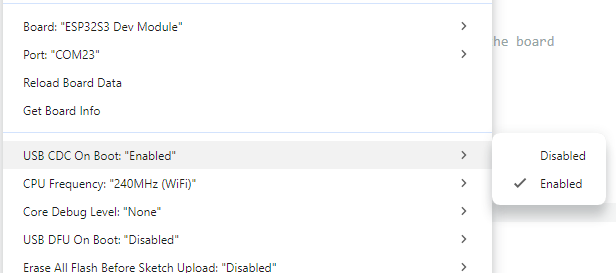
There is a build option that determines whether the loaded code includes a USB comms device or not.

If this isn’t set (i.e. “disabled”) then Serial goes to UART0 and the serial monitor has to be connected to the “COM” USB port.

If this is set (i.e. “enabled”) then Serial goes to USBSerial and the serial monitor can be connected to the “USB” USB port.

Note: there is some ESP32 start-up debug information that will always go to UART0 on boot regardless of this setting.

Analog Input

One quirk of the ESP32 Arduino environment and the ADC mapping means that the ADCs are mapped as follows:

  • ESP32 ADC1 peripheral: channels 0 to 9 = GPIO 1 to GPIO 10 = Arduino A0 to A9
  • ESP32 ADC2 peripheral: channels 0 to 9 = GPIO 11 to GPIO 20 = Arduino A10 to A19

This can be seen in the board definitions file for the Arduino ESP32 core: https://github.com/espressif/arduino-esp32/blob/master/variants/esp32s3/pins_arduino.h

Specific GPIO

We can also see the following from pins_arduino.h:

  • TX/RX = GPIO 43, 44 (as might be expected).
  • SDA/SCL = GPIO 8, 9
  • SPI = GPIO 10, 11, 12, 13

We can also see a series of Tn pin definitions for the touch pins:

  • T1-14 = GPIO 1-14

RGB and LED_BUILTIN

Also, whilst perusing the same file, I noticed the following comment:

// Some boards have too low voltage on this pin (board design bug)
// Use different pin with 3V and connect with 48
// and change this setup for the chosen pin (for example 38)
#define PIN_RGB_LED 48
// BUILTIN_LED can be used in new Arduino API digitalWrite() like in Blink.ino
static const uint8_t LED_BUILTIN = SOC_GPIO_PIN_COUNT + PIN_RGB_LED;
#define BUILTIN_LED LED_BUILTIN // backward compatibility
#define LED_BUILTIN LED_BUILTIN // allow testing #ifdef LED_BUILTIN
// RGB_BUILTIN and RGB_BRIGHTNESS can be used in new Arduino API rgbLedWrite()
#define RGB_BUILTIN LED_BUILTIN
#define RGB_BRIGHTNESS 64

This is recognising that pin 48 was used by default for the RGB LED, but because of the possibility of pins 47 and 48 being configured for 1.8V operation for certain SPI flash memory configurations, means that it doesn’t work in some cases. Presumably this is why the official boards now use pin 38 for the RGB LED instead.

Note, I don’t know why LED_BUILTIN = SOC_GPIO_PIN_COUNT + PIN_RGB_LED, but I’ve seen elsewhere, in cores/esp32/esp32-hal-rgb-led.c:

#ifdef RGB_BUILTIN
pin = pin == RGB_BUILTIN ? pin - SOC_GPIO_PIN_COUNT : pin;
#endif

The provided BlinkRGB.ino example works fine with the official board and my clone. Both boards are configured as follows:

  • Connect via USB port (not the COM port).
  • Board: ESP32S3 Dev Module
  • All other settings: Defaults

And using Serial.print for PIN_RGB_LED confirms that the RGB is on GPIO 48 for both my boards.

I2C GPIO

In terms of I2C, it is possible to select which pins to use, if the defaults (8, 9) are not desired. to do this, just pass some pin numbers into the Wire.begin call as follows:

Wire.begin(I2C_SDA, I2C_SCL);

Note that this is different to how this is done on a RP2040 which has its own setSDA() and setSCL() functions. At least in the unofficial core. I don’t know if this is even possible with the “official” RP2040 Arduino core, but I’m getting off-topic…

Closing Thoughts

For some reason, from what I’d read I was expecting an obvious leap in performance moving from an ESP32 to a ESP32S3, but now I’m not so sure it will make much difference.

I’ll just have to give things a go and see what happens!

Kevin

#esp32 #ESP32s3 #ifdef #pcb
Waveshare Zero, Pimoroni Tiny, and Neopixels

I want to revisit my Forbidden Planet “Krell” Display looking at an alternative way to do the electronics. In particular, I’m looking at how I might embed a microcontroller in each display. T…

Simple DIY Electronic Music Projects