@trankten

#define FALSE (void*)0

FALSE == NULL

But... I must say I am a bit disappointed. The PostScript authors were the kind of people who write C, but want it to look like some other language:

#define private static
...
#define procedure integer /* actually void */
...
private procedure PSBegin()
{
...

Not likely to be a very entertaining read;)

#llm #linux #programming #hdd

Recently they suddenly brought several block devices, should I throw them to the dump or can I still use them.

I thought to run the old-school badblocks -svw, but it turned out that they forgot about it and still haven't switched to 64-bit addressing:

badblocks -svw /dev/sdb badblocks: Value too large for defined data type invalid end block (5860522584): must be 32-bit value

Given this and lack of free time and desire to write fairly boring code, set the task deepssek v3.1 terminus, here's what I got (typos and critical logic errors in the code were fixed):

1:

#define _GNU_SOURCE #include <stdio.h> #include <stdlib.h> #include <unistd.h> #include <stdint.h> #include <fcntl.h> #include <sys/ioctl.h> #include <linux/fs.h> #include <scsi/sg.h> #include <errno.h> #include <string.h> #include <sys/mman.h> #include <time.h> #define LOCAL_BLOCK_SIZE (1024*1024) // 1MB блоки #define SECTOR_SIZE 512 // Структура для SCSI команды WRITE LONG (ремэппинг) struct write_long_cmd { unsigned char opcode; // 0xE3 для WRITE LONG unsigned char obsolete; unsigned char lba_high; unsigned char lba_mid; unsigned char lba_low; unsigned char sector_count; unsigned char control; }; // Получение размера устройства в байтах uint64_t get_device_size(int fd) { uint64_t size; if (ioctl(fd, BLKGETSIZE64, &size) == -1) { perror("BLKGETSIZE64 failed"); exit(1); } return size; } // Синхронное чтение с прямым I/O ssize_t direct_read(int fd, void *buf, size_t count, off_t offset) { return pread(fd, buf, count, offset); } // Синхронная запись с прямым I/O ssize_t direct_write(int fd, void*buf, size_t count, off_t offset) { return pwrite(fd, buf, count, offset); } // Отправка SCSI команды для ремэппинга сектора int remap_sector(int sg_fd, uint64_t lba) { struct write_long_cmd cmd = { .opcode = 0xE3, // WRITE LONG .lba_high = (lba >> 16) & 0xFF, .lba_mid = (lba >> 8) & 0xFF, .lba_low = lba & 0xFF, .sector_count = 1, .control = 0 }; unsigned char sense_buffer[32]; struct sg_io_hdr io_hdr = { .interface_id = 'S', .dxfer_direction = SG_DXFER_TO_DEV, .cmd_len = sizeof(cmd), .mx_sb_len = sizeof(sense_buffer), .dxfer_len = SECTOR_SIZE, .dxferp = NULL, // WRITE LONG без передачи данных .cmdp = (unsigned char*)&cmd, .sbp = sense_buffer, .timeout = 30000 // 30 секунд }; return ioctl(sg_fd, SG_IO, &io_hdr); } int main(int argc, char*argv[]) { if (argc != 2) { fprintf(stderr, "Использование: %s /dev/sdX\n", argv[0]); return 1; } // Открываем устройство для прямого I/O int fd = open(argv[1], O_RDWR | O_DIRECT | O_SYNC); if (fd == -1) { perror("Ошибка открытия устройства"); return 1; } // Открываем SCSI generic интерфейс для ремэппинга int sg_fd = open(argv[1], O_RDWR); if (sg_fd == -1) { perror("Ошибка открытия SCSI интерфейса"); close(fd); return 1; } uint64_t device_size = get_device_size(fd); uint64_t total_blocks = device_size / LOCAL_BLOCK_SIZE; printf("Размер устройства: %lu байт (%lu блоков по 1MB)\n", device_size, total_blocks); // Выделяем выровненную память для прямого I/O void *buffer; if (posix_memalign(&buffer, 4096, LOCAL_BLOCK_SIZE) != 0) { perror("Ошибка выделения выровненной памяти"); close(fd); close(sg_fd); return 1; } memset(buffer, 0, LOCAL_BLOCK_SIZE); int bad_sectors_found = 0; int pass = 1; do { printf("Проход %d: сканирование %lu блоков...\n", pass, total_blocks); bad_sectors_found = 0; for (uint64_t block = 0; block < total_blocks; block++) { off_t offset = block* LOCAL_BLOCK_SIZE; // Вывод прогресса каждые 1000 блоков if (block % 1000 == 0) { printf("Прогресс: %.2f%%\r", (double)block*100.0 / total_blocks); fflush(stdout); } // Чтение блока 1MB ssize_t bytes_read = direct_read(fd, buffer, LOCAL_BLOCK_SIZE, offset); if (bytes_read != LOCAL_BLOCK_SIZE) { printf("\nОшибка чтения блока %lu (смещение: 0x%lx)\n", block, offset); // Детальное сканирование посекторно for (int sector = 0; sector < LOCAL_BLOCK_SIZE/SECTOR_SIZE; sector++) { off_t sector_offset = offset + sector *SECTOR_SIZE; uint64_t lba = sector_offset / SECTOR_SIZE; ssize_t sector_read = direct_read(fd, buffer, SECTOR_SIZE, sector_offset); if (sector_read != SECTOR_SIZE) { printf(" Нечитаемый сектор LBA %lu (ошибка: %s)\n", lba, strerror(errno)); // Перезапись сектора с ремэппингом int retry = 0; while (1) { retry++; // Сначала пытаемся обычной записью ssize_t written = direct_write(fd, buffer, SECTOR_SIZE, sector_offset); if (written == SECTOR_SIZE) { printf(" Сектор перезаписан успешно (попытка %d)\n", retry); break; } // Если обычная запись не сработала, пробуем ремэппинг if (remap_sector(sg_fd, lba) == 0) { printf(" Ремэппинг сектора выполнен (попытка %d)\n", retry); break; } printf(" Ошибка перезаписи/ремэппинга, повтор...\n"); usleep(100000); // 100ms задержка между попытками } bad_sectors_found++; // Проверяем, что сектор теперь читается sector_read = direct_read(fd, buffer, SECTOR_SIZE, sector_offset); if (sector_read == SECTOR_SIZE) { printf(" Сектор восстановлен успешно\n"); } else { printf(" ВНИМАНИЕ: сектор все еще не читается!\n"); } } } } } printf("\nПроход %d завершен. Найдено нечитаемых секторов: %d\n", pass, bad_sectors_found); pass++; } while (bad_sectors_found > 0); printf("Восстановление завершено. Все сектора читаются.\n"); free(buffer); close(fd); close(sg_fd); return 0; }

2:

#define _GNU_SOURCE #include <stdio.h> #include <stdlib.h> #include <unistd.h> #include <fcntl.h> #include <sys/ioctl.h> #include <linux/fs.h> #include <errno.h> #include <stdint.h> const uint16_t SECTOR_SIZE = 512; const uint8_t BLOCK_SIZE_MB = 1; const uint32_t _BLOCK_SIZE = (BLOCK_SIZE_MB*1024*1024); const uint32_t WRITE_SIZE = (BLOCK_SIZE_MB*1024*1024); const uint16_t RETRIES = 1024; typedef struct { int fd; unsigned long long device_size; unsigned long long current_pos; } disk_ctx_t; // Получение размера устройства int get_device_size(int fd, unsigned long long *size) { if (ioctl(fd, BLKGETSIZE64, size) == -1) { return -1; } return 0; } // Чтение блока с проверкой ошибок int read_block(int fd, void*buffer, unsigned long long offset, size_t size) { if (lseek(fd, offset, SEEK_SET) == -1) return -1; ssize_t bytes_read = read(fd, buffer, size); return (bytes_read == (ssize_t)size) ? 0 : -1; } // Запись блока int write_block(int fd, void*buffer, unsigned long long offset, size_t size) { if (lseek(fd, offset, SEEK_SET) == -1) return -1; ssize_t bytes_written = write(fd, buffer, size); return (bytes_written == (ssize_t)size) ? 0 : -1; } // Поиск первого битого сектора в блоке unsigned long long find_bad_sector(int fd, unsigned long long block_start) { unsigned char sector[SECTOR_SIZE]; for (unsigned long long sector_offset = 0; sector_offset < _BLOCK_SIZE; sector_offset += SECTOR_SIZE) { if (read_block(fd, sector, block_start + sector_offset, SECTOR_SIZE) == -1) { return block_start + sector_offset; } } return 0; // Все сектора читаются } // Восстановление проблемной области int repair_area(int fd, unsigned long long bad_sector) { unsigned char *repair_buffer = calloc(0xaa, WRITE_SIZE); if (!repair_buffer) return -1; for (int attempt = 0; attempt < RETRIES; attempt++) { if (write_block(fd, repair_buffer, bad_sector, WRITE_SIZE) == 0) { free(repair_buffer); return 0; // Успех } usleep(100000); // 100ms задержка между попытками } free(repair_buffer); return -1; // Все попытки провалились } int main(int argc, char*argv[]) { if (argc != 2) { fprintf(stderr, "Использование: %s <устройство>\n", argv[0]); return 1; } int fd = open(argv[1], O_RDWR | O_DIRECT); if (fd == -1) { perror("Ошибка открытия устройства"); return 1; } disk_ctx_t ctx = {0}; ctx.fd = fd; if (get_device_size(fd, &ctx.device_size) == -1) { perror("Ошибка получения размера устройства"); close(fd); return 1; } printf("Размер устройства: %llu байт\n", ctx.device_size); unsigned char *block_buffer = aligned_alloc(4096, _BLOCK_SIZE); if (!block_buffer) { perror("Ошибка выделения памяти"); close(fd); return 1; } int bad_sectors_found = 0; int pass = 1; do { printf("Проход %d...\n", pass++); bad_sectors_found = 0; ctx.current_pos = 0; while (ctx.current_pos < ctx.device_size) { size_t read_size = (ctx.device_size - ctx.current_pos < _BLOCK_SIZE) ? ctx.device_size - ctx.current_pos : _BLOCK_SIZE; if (read_block(fd, block_buffer, ctx.current_pos, read_size) == -1) { printf("Ошибка чтения блока по смещению %llu\n", ctx.current_pos); unsigned long long bad_sector = find_bad_sector(fd, ctx.current_pos); if (bad_sector) { printf("Найден битый сектор по смещению %llu\n", bad_sector); if (repair_area(fd, bad_sector) == 0) { printf("Сектор %llu восстановлен\n", bad_sector); } else { printf("Не удалось восстановить сектор %llu\n", bad_sector); } bad_sectors_found++; ctx.current_pos = bad_sector + WRITE_SIZE; } else { ctx.current_pos += read_size; } } else { ctx.current_pos += read_size; } // Прогресс каждые 1GB if (ctx.current_pos % (1024*1024*1024) == 0) { printf("Прогресс: %.1f%%\n", (double)ctx.current_pos / ctx.device_size* 100); } } } while (bad_sectors_found > 0); free(block_buffer); close(fd); printf("Проверка завершена\n"); return 0; }

Of course, the code is far from ideal, but it basically solves the set task.

pleroma.dark-alexandr.net

@bshanks Ah, I found it in Xcode.app/Contents/Developer/Platforms/MacOSX.platform/Developer/SDKs/MacOSX.sdk/System/Library/Frameworks/Kernel.framework/Versions/A/Headers/arm/cpuid.h

/* H17G Hidra e-Core. */
#define CPU_PART_ECORE_HIDRA 0x62

/* H17G Hidra p-Core. */
#define CPU_PART_PCORE_HIDRA 0x63

@bshanks Where did you find the connection between CPUFAMILY_ARM_HIDRA and H17G? In Xcode.app/Contents/Developer/Platforms/MacOSX.platform/Developer/SDKs/MacOSX.sdk/usr/include/mach/machine.h I see this:

#define CPUFAMILY_ARM_HIDRA 0x1d5a87e8

I can't figure out how 0x1d5a87e8 would become H17G.

Hackspace LED Panels

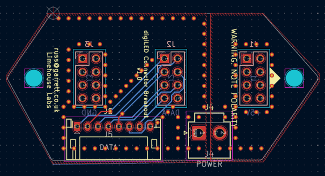
I was lucky enough to get some 16×64 LED Panels in a Hackspace giveaway, courtesy of Limehouse Labs, London, but have only recently started to look at how to use them.

As usual, these are my “notes to self” after attempting to use the suggested libraries and not really getting how they work, so I ended up doing what I often do – reinventing this particular wheel so I really understand what is going on.

https://makertube.net/w/uMhG7dcEs9D5BYmsXF7MVK

References:

And the main devices on the panels are the MBI5034 shift register ICs.

Introduction

The best description of the bit stream required to drive them can be found here: https://wiki.london.hackspace.org.uk/view/LED_tiles_V2

It is a bit complicated…

  • There are two address lines, which feed into a HC138 3 to 8 line decoder (the third input is ignored), so together they select one of four blocks of four lines of LEDs.
  • There are two data lines into the MBI5034 shift registers, 24 per line, which access the top and bottom half of the display in turn.
  • A full stream of data covers two full lines of 64 RGB LEDs.
  • Data has to be sent to individual R, G and B LEDs.

The general idea is to send the bit pattern for both D1 and D2 at the same time for a specific address (0, 1, 2 or 3) and keep clocking the appropriate bits out to the device. Then change the address and do it again until all four addresses have been covered.

The address isn’t really an address as such – it is more of a matrix “scan line” in that the LEDs are matrixed so that only the LEDS with the common line corresponding to that “address” will be activated at any one time. As there are four lines, the whole panel can only be scanned using persistence of vision, illuminating each scan line in turn.

To drive multiple panels means adding their D1 and D2 lines to the system too, but sharing all other signals. Most approaches I’ve seen encode all 8 bits or each of the eight Dn lines into a single byte and then sent those out in parallel to four panels at the same time.

If the data is stored in a frame buffer in “4 panel Dn ready format” then driving four panels isn’t really that much slower than driving one.

Some numbers:

  • There are 16 x 64 RGB LEDs per panel = 1024 RGB LEDs.
  • Each RGB LED is actually three individual R, G and B LEDs, so there are 3072 LEDs to drive per panel.
  • Each MBI5034 has 16 outputs, so can drive 16 individual LEDs directly.
  • There are 48 MBI5034 chips per panel, 24 per data line, so they have to drive 64 LEDs each…

So on that last point – as already mentioned, the 74HC138 8-line decoder links the address lines A0, A1 to four outputs (Y0, Y1, Y2, Y3). This is used to “select” one of four blocks of 16 LEDs per MBI5034. Once each address has been scanned, each MBI5034 can be seen to be driving the equivalent of 4 rows of 16 LEDs in total, which is the required 64 LEDs each.

Apparently each MBI5034 will directly address a single LED colour: R, G or B. So 48 of these, driving 16 R, 16 B, 16 G means they can directly address 768 LEDs, or 256 R, G, and B LEDs. Again, doing this four times gives the full 1024 RGB LED panel.

This all means that the panel is logically arranged as two 128 x 4 matrices, physically arranged across two rows of 64 LEDs each. The full 16 rows of 64 LEDS are selected by the following combinations of D1, D2, A0, A1:

A0A1D1 = 1D2 = 100Rows 0, 4Rows 8, 1201Rows 1, 5Rows 9, 1310Rows 2, 6Rows 10, 1411Rows 3, 7Rows 11, 15

A further complication is that each row itself is encoded not as 2 sets of 64 RGB values, but as 8 sets of [16-bit B + 16-bit R + 16 bit G] values with the 16-bit B, G, R values encoding 8 of each colour LED on the first row, and then 8 on the second row.

The upshot of all this is that 384 bits of data must be streamed out to the shift registers for each address, but only two lines per half-panel can be illuminated at any one time. As I say, persistence of vision is required to illuminate the entire panel.

The basic algorithm required to display something on the panel will thus be as follows:

FOR EACH bank (address = 0, 1, 2, 3):
Clock out 384 bits of BGR data covering two rows of 64 LEDs.
Do this for both D1 and D2 at the same time, so illuminating four rows in total.
IF using more than one panel, also do this for D1 and D2 for all other panels too

Hardware

I had some of the interface PCBs made, that were described here: https://github.com/limehouselabs/led-screens/tree/main/panel-connector

The central block is mapped over to a JST PH 8-way connector as follows:

D1LATA1N/CD2OEA0CLK

JST PH Connector:

  • GND
  • CLK
  • LAT
  • OE
  • A1
  • A0
  • D2
  • D1

The board provides screw terminals for a higher current 5V supply.

Various estimates suggest one panel could require up to 8A with all LEDS on at full brightness, so I’m using a 40A 5V supply. The main issue is ensuring the Arduino’s GND and the GND of the power supply are linked, which this PCB does.

Arduino “Shield”

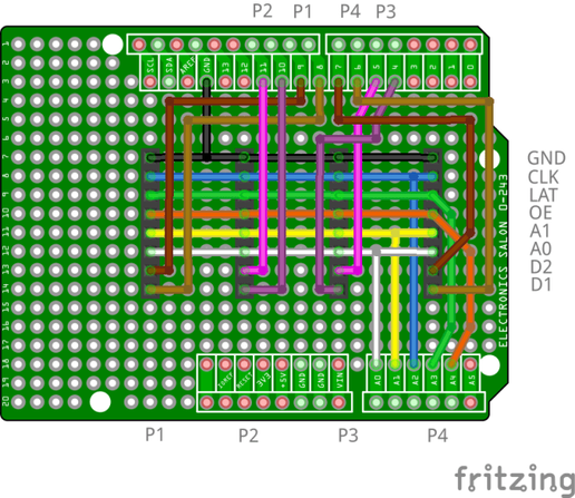
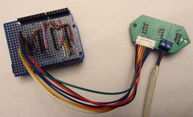
After getting fed up with jumper wires falling out of solderless breadboards, I eventually soldered up a simple Arduino proto shield able to support up to four panels.

This maps the panel signals onto Arduino pins as follows:

ArduinoPanel(s)A0A0 (all panels)A1A1 (all panels)A2CLK (all panels)A3LAT (all panels)A4OE (all panels)D4D5 (D1 panel 3)D5D6 (D2 panel 3)D6D7 (D1 panel 4)D7D8 (D2 panel 4)D8D1 (D1 panel 1)D9D2 (D2 panel 1)D10D3 (D1 panel 2)D11D4 (D2 panel 2)

The slightly odd mapping of Arduino digital outputs to panels will become clear when we look at the code.

Using this with a ready-made JST PH connector-to-jumper-wire cable and then crimping Dupont header pins onto it seems to do the job (or so I thought).

Driver Code

I started with the Arduino code linked to above. This is written for an ATMega32U4 based Arduino and uses direct Port IO to access the panels.

I wanted to use an Uno or Nano, so I started to port this over to an ATMega328, but just could not get anything working at all, so in the end I decided to go back to basics and rewrite the code from first principles so I knew what was going on.

The basic design of the code will be as follows:

  • An interrupt-driven routine to take a buffer representing each LED that is already in the correct format for the panels, and streams this data out to the panels on a regular basis.
  • As mentioned, a frame buffer that can be written to that is already “panel aware”, but has a simple interface using (x, y, colour) to set a pixel.
  • Use direct PORTIO where possible to ensure quick updating of the signals when streaming out to the panels.

Driving Four Panels at Once

All signals apart from D1 and D2 are common to both halves of each panel. This means that once the code has processed the address signals, LAT, CLK and OE, there is no reason not to then process D1 and D2 for all existing panels in parallel.

This can be done pretty efficiently on an Arduino by mapping the eight Dn signals onto a single Arduino port and using PORT IO to write out all four values at once.

It isn’t quite that simple however, as there isn’t a single 8-bit port on an Arduino that isn’t used for something else too, so I’m going to do it in two halves, using PORTB and PORTD as follows:

Panel DnArduino DnArduino PORTP1 D18PORTB 0P1 D29PORTB 1P2 D110PORTB 2P2 D211PORTB 3P3 D14PORTD 4P3 D25PORTD 5P4 D16PORTD 6P4 D27PORTD 7

Using this mapping, an 8-bit value can be stored in the framebuffer per LED as follows:

b7 6 5 4 3 2 1 0
D8 D7 D6 D5 D4 D3 D2 D1
P4 P3 P2 P1

And then when it comes to writing it out via the Arduino digital IO it can be done in two instructions:

PORTB = (PORTB & (~0x0F)) | (data & 0x0F);
PORTD = (PORTD & (~0xF0)) | (data & 0xF0);

This is mapping the low 4 bits of the data value onto the low 4 bits of PORTB and the top 4 bits of the data value onto the top 4 bits of PORTD.

The Writing Protocol

Implementing the protocol described in the various references, I’m after the following basic structure:

  • Clock out the data on all 8 Dn lines using PORTIO.
  • Blank the screen and LATch the data.
  • Set A0/A1 accordingly to select the correct row of LEDs via the matrix.
  • Unblank the screen.

The entire routine for updating the display is as follows.

void panelScan (void) {
for (int i=0; i<FB_BITS; i++) {
setDataOutput(fb[bank][i]);
// Pulse the clock
CLKSET;
CLKCLR;
}

// Blank display
OESET; // active LOW

// Set address
SETADDR(bank);

// Toggle latch
LATSET;
LATCLR;

// Unblank display
OECLR; // Active LOW

bank++;
if (bank >= FB_BANKS) bank = 0;
}

This processes a single address per scan, so four scans are required, with persistence of vision, to illuminate the entire display.

The various macros, such as CLKSET, CLKCLR and so on, are defined for individual bit manipulation PORTIO as follows:

#define CLKSET {PORTC = (PORTC & (~0x04)) | 0x04;} // A2
#define CLKCLR {PORTC = (PORTC & (~0x04)) ;}

SETADDR is a special macro that sets both A0 and A1 at the same time.

#define SETADDR(x) {PORTC = (PORTC & (~0x03)) | (x & 0x03);} // A0/A1

setDataOutput() is an inline routine that has the two previously mentioned lines in it to set PORTB and PORTD.

The Framebuffer

There is one unexplained item in that previous routine. The value passed into setDataOutput is an entry from the frame buffer – the “panel ready data format” I mentioned previously.

Here is my description of how the framebuffer works from the code itself followed by my setPixel routine that implements it.

// The panel is addressed as a string of bits, representing 64 R,G,B values.
// but the ordering is a little odd.
//
// For each address (A1/A0) a string of bits represents two rows of LEDs.
// 64 * 2 * 3 = 384 bits of information.
//
// Ordering is as follows:
// [ BBBBBBBB BBBBBBBB GGGGGGGG GGGGGGGG RRRRRRRR RRRRRRRR ] * 16
// Row0 0-7 Row4 0-7 Row0 0-7 Row4 0-7 Row0 0-7 Row4 0-7 Repeat for 8-15,16-23,24-31
//
// This addresses rows 0 and 4 when A1/A0 = 00:
// A1 A0 1st Row 2nd Row
// 0 0 0 4
// 0 1 1 5
// 1 0 2 6
// 1 1 3 7
//
// The bit data is streamed out on D1 for the top half of the panel.
// The same principle and format bit stream is streamed out on D2 for the second half.
// Any additional panels will have their own D1/D2 lines and the same format bit streams.
//
// All this means that the (x,y) coordinates must map onto the frame buffer as follows:
// y = b76543210
// ++--- A1/A0 lines 0-3
// +----- First or second row
// +------ D1 or D2
// ++------- Panel number for four panels 0-3
// ++--------- Only required if more than four panels (up to 16)
//
// x = b76543210
// +++--- Position within a block of 8 LEDs
// +++------ Which block of 8 to address
//
// Mapping the x coord is more complex though as the position relates to:
// - 1st/2nd Row determines which block of 8 within each colour.
// - Colour B/G/R determines which pair of blocks of 8.
//
// Led Idx within a block = x[2:0]
// Block Idx in frame buffer = x[5:3] * (16+16+16)
// So LED position = BlockIdx + 8 (if 2nd Row) + 16 (if G) + 32 (if R) + LedIdx
//
// One final complication. The framebuffer is a set of bytes that maps onto
// the different halves of different panels, so which bit in the framebuffer
// gets set depends on the panel number and D1/D2 selection.
//
// Assuming a simple D8-D1 mapping, this means the following:
// b76543210
// ++--- D2/D1 Panel 1
// ++----- D2/D1 Panel 2
// ++------- D2/D1 Panel 3
// ++--------- D2/D1 Panel 4
//
void setPixel (int x, int y, panelcolour col) {
if ((x<0) || (x>=64) || (y<0) || (y>=64)) {
// Only 4x 16*64 panels supported
return;
}
int a1a0 = y & 0x03; // bank
int row4 = y & 0x04 ? 8 : 0;
int d1d2 = y & 0x08;
int panel = y >> 4; // panel 0..15; only 0..4 supported
int bitIdx = y >> 3; // panel no + d1/d2
int led8 = x & 0x07;
int block = x >> 3;

// Determine the bit to act on for the four panels D1-D2
uint8_t bit = (1<<bitIdx);
int off = block * 48 + row4 + led8; // Location of B LED to act on
if (col & BITBLUE) {
fb[a1a0][off] |= bit;
} else {
fb[a1a0][off] &= ~bit;
}
if (col & BITGREEN) {
fb[a1a0][off+16] |= bit;
} else {
fb[a1a0][off+16] &= ~bit;
}
if (col & BITRED) {
fb[a1a0][off+32] |= bit;
} else {
fb[a1a0][off+32] &= ~bit;
}
}

Understanding how the y value turns into a panel, Dn, and An number is perhaps best shown with an example. The following shows how incrementing the y coordinate maps onto panels.

y=b7654 3210 A D P1
0000 0000 0 1
0000 0001 1 1
0000 0010 2 1
0000 0011 3 1
0000 0100 0 1
0000 0101 1 1
0000 0110 2 1
0000 0111 3 1

0000 1000 0 2 P1
...
0000 1111 3 2

0001 0000 0 1 P2
...
0001 1111 3 2 P2

0010 0000 0 1 P3
...
0010 1111 3 2 P3

0011 0000 0 1 P4
...
0011 1111 3 2 P4

01xx xxxx x x P5-P8
1xxx xxxx x x P9-P15

Following the x coordinate mapping is ok once the idea of using the coordinate value to orient to the start of the 48-bit triple of 16 B, 16 G and 16 R values across the two rows is figured out. Then it is a case of calculating the offset within the referenced 48-bit triple as per the comments in the code above.

Set Brightness

There is a special command word that can be used to set the overall brightness of the driver chips. Sending this to all 48 chips on a panel will set the brightness for the whole panel.

Full details can be found in the “dimming the panel” section here: https://wiki.hackhitchin.org.uk/index.php?title=LED_panel_interface and in the MBI5034 datasheet (see “Current Gain Adjustment”).

This is the brightness function:

void setBrightness (uint8_t brightpercent) {
uint8_t bright;
if (brightpercent <= 12) {
bright = 0;
} else if ((brightpercent > 12) && (brightpercent < 100)) {
// Scale 12-100% between 0 and default value
bright = (brightpercent - 12) * 0x2B / 88;
} else {
bright = 0x2B;
}

uint16_t ctrl = 0b0111000101000000 | bright;

OESET; // active LOW
LATCLR;
CLKCLR;

for (int a=0; a<FB_BANKS; a++) {
SETADDR(a);
for (int c=0; c<24; c++) {
for (int b=15; b>=0; b--) {
if ((ctrl & (1<<b)) == 0) {
setDataOutput(0);
} else {
setDataOutput(0xFF);
}
if ((c == 23) && (b < 4)) {
LATSET;
} else {
LATCLR;
}
CLKSET;
CLKCLR;
}
}
}
LATCLR;
}

Notes:

  • The control word is streamed out MSbit first.
  • The LATch is held for the last four bits of the write to the last chip.
  • The same pattern is written to all Dn bits at the same time.
  • Brightness 0 (b000000) corresponds to 12.5% brightness.
  • Brightness 63 (b111111) corresponds to 200% brightness.
  • The default is 0x2B (b101011) which corresponds to a “gain” of 1 (see datasheet), so I’ve taken that to be considered “normal” or 100% brightness.
  • My code only accepts values from 12% to 100%. I’ve not allowed it to go up to 200%.

There is one added complication though – whilst this is going on, the normal scanning should be paused to ensure it doesn’t interfere.

Strictly speaking, the setBrightness routine should pause briefly too, to ensure any existing scanning is complete, but as the interrupt is higher priority than the running code, it should always complete first anyway.

Code Summary

I’ve ended up with the following routines in my code:

void panelInit (void);
void panelScan (void);
void panelClear (bool on=false);
void setPixel (int x, int y, panelcolour col);
panelcolour getPixel (int x, int y);
void setBrightness (uint8_t brightpercent);

To use these requires the following basic setup:

#include <TimerOne.h>
#include "LEDPanel.h"

void setup() {
panelInit();
panelClear();

Timer1.initialize(5000); // 200Hz
Timer1.attachInterrupt(panelScan);

setBrightness (BRIGHTNESS_MIN);
}

#define DEL 5
void loop() {
for (int x=0; x<64; x++) {
for (int y=0; y<64; y++) {
setPixel(x, y, led_blue);
delay(DEL);
setPixel(x, y, led_green);
delay(DEL);
setPixel(x, y, led_red);
delay(DEL);
setPixel(x, y, led_white);
delay(DEL);
}
for (int y=0; y<64; y++) {
setPixel(x, y, led_black);
}
}
}

Notes:

  • This uses the TimerOne library to generate the panelScan() regular update.
  • I’ve configured the scan for 200Hz.
  • The loop illuminates each column in turn, from top to bottom.
  • This assumes the use of four panels as described above.

Find the full code on GitHub here.

Expanding to Four Panels

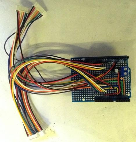
When it came to it, wiring up four panels wasn’t going to work with the cables and shield I already had, I would have had to have made some longer ones, so in the end I just soldered up a slightly different arrangement of the Arduino shield.

I’ve also added some screw terminals to allow the Arduino to be powered directly via its 5V pin from the main 5V power supply to the panels. I’ve added a 220uF capacitor to attempt to give some stability to the power as the LEDs turn on and off.

I experimented with some 3D printed connectors but couldn’t get anything that connected snugly enough to keep the panels together, so in the end just nailed four panels to a piece of wood as shown.

I have test code for the following:

  • To step down the brightness from full to minimum.
  • To illuminate each column of LEDs in turn.
  • To draw a basic Mandelbrot set.
  • To Conway’s Game of Life.

I wasn’t able to capture the “all pixels on” Mandelbrot without the scan lines becoming apparent. I’m not entirely sure why this would be different compared to when it is building up the set or running the Game of Life, but it does. I’ll have to have a think about that one!

Also, I don’t have enough memory on an Uno for a full dual-buffer grid for the Game of Life, so I’m using the pixel buffer itself as the state of the “live” display and have another buffer to calculate the updated values. To have all this on an Uno, I’ve had to limit the display to 52 rows rather than the full 64. Even that only gives me 62 bytes free!

Update: the latest version of the code includes an option to fade dying cells out using different colours. This is shown in the video at the start of this post.

Other Notes

It took me ages to get this working – almost a week on and off. I tried everything – checking the protocol with a scope; working through the interrupt performance and timing requirements; dropping back to a simple test case; ultimately soldering up that interface board and verifying the power supply. I even went right back to first principles and coded up my own routines that I could fully understand.

But I couldn’t get the panels to work.

In the end I took one panel apart and started poking around with an oscilloscope.

Interestingly there are two HC245 line buffers directly off the interface connection. One appears to produce four OE lines and four CLK signals. The other appears to have the address, data and other signals.

It turns out that my crimped connector had a dodgy link on the LATch wire, so although I could see all the correct signals happening at the Arduino end, the LAT signal was never actually making it to the panel!

That will teach me to check first principles and not assume anything.

Or rather, I suspect it won’t and I’ll continue to have plenty more similar issues as I move forward.

As usual a massive thanks to those who have worked out how to do all of the above, and a big thank you to Limehouse Labs for the large giveaway in the first place!

Kevin

#arduinoUno #define #include #led #RGB

Shifting Fortunes and Tactical Battles in Bundesliga 2The latest round of Bundesliga 2 matches delivered a mix of compelling narratives and critical shifts in t... https://news.osna.fm/?p=21610 | #news #comeback #define #draws #matchday
Draws and a Comeback Define Matchday - Osna.FM

Thrilling 2. Bundesliga action! Elversberg and Hannover draw 2-2, while Preußen Münster secure a home victory over Holstein Kiel.

Osna.FM
#define TRUE rand()%100

@Aradayn @bagder Yeah I could understand it if the code contained

#define __AMIGA__ 3000

but it's not defining anything, it's just checking for it, and any fault therefore should lie with the environment it might be compiled in.

I read through the TIOBE standard doc (https://www.tiobe.com/files/TIOBEQualityIndicator_v5_0.pdf) and was initially thinking "Well, this isn't too bad, and it makes a lot of good points", but if TIOBE doesn't actually understand the standards, then they're not qualified to be doing this.

@sodiboo @bagder yeah. honestly it should really just only be checking if you #define macros with such reserved name patterns in your own code, not if you check an existing one defined based on the architecture, platform, compiler, libc, etc etc.