Arduino and AY-3-8910 – Part 2

Following on from my initial experiments in Arduino and AY-3-8910 this post looks at the sound generation capabilities in a little more detail and adds some basic MIDI control.

https://makertube.net/w/3CxNBDKu5Gm6MQzMcLZYz6

Warning! I strongly recommend using old or second hand equipment for your experiments.  I am not responsible for any damage to expensive instruments!

These are the key tutorials for the main concepts used in this project:

If you are new to Arduino, see the Getting Started pages.

Parts list

  • Arduino Uno.
  • AY-3-8910 chip.
  • Either GadgetReboot’s PCB or patch using solderless breadboard or prototyping boards.
  • 5V compatible MIDI interface.
  • Jumper wires.

AY-3-8910 Sound Generation

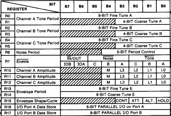
The most basic means of sound generation is to use the three tone generators to generate square waves at a frequency set using the on-chip registers (note in the following data from the datasheet, the R numbers are in octal – so there are 16 registers in total):

I don’t plan to get into the ins-and-outs of how to interface to the chip, instead I’ll link off to some excellent discussions here:

The frequency registers have a 12-bit resolution, spread over two 8-bit registers as shown below.

The datasheet tells us how to calculate the value to write to the register for a specific frequency:

  • Reg Value = System Clock / (16 * frequency)

For a 1MHz clock, the register value is thus 62500 / frequency, so the higher the frequency, the lower the register value. This means that concert A at 440Hz requires the value 62500 / 440 = 142, so:

  • R1 = 142 >> 8;
  • R0 = 142 & 0xFF;

For a 1MHz clock, the range of frequencies goes from 1MHz / 16 to 1 MHz / (16 * 4095) or ~62.5kHz to 15 Hz

The AY3891x library has a set of definitions that already defines the frequencies for each MIDI note from C0 to B8.

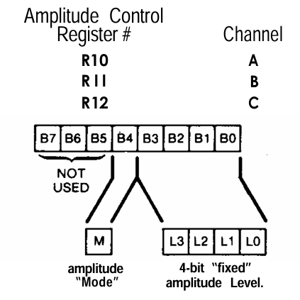
The volume for the note is set in another register:

When Mode=0, the amplitude is set by the 4-bit fixed level. When Mode=1, the amplitude is controlled by the built-in envelope generator.

The envelope generator is a “global” setting for all channels, so for finer control, people often wrote their own envelope generator, manipulating the volume levels directly.

The datasheet describes the four parameters required to define an envelope:

Envelopes have a cycle time, which is set by R13 and R14 in a similar way to the frequency. This time the formula is:

  • Reg value = System Clock / (256 * env frequency)

Once again this is split over two registers, but this time supports a full 16-bit value.

There are graphical representations of what the combinations of the envelope bits mean, but I must confess I’m not entirely sure I understand them all and some don’t seem to sound, at least at the frequency I’ve chosen.

The Circuit

I’m reusing the PCB from GadgetReboot from Part 1, but this time I’ve added the button in (it is connected to A5 and GND) and added headers to the UART connection.

Unfortunately the UART only has GND, TX, RX – to use it with one of my Arduino MIDI Interfaces also requires a 5V connection, so I’ve taken that from the SD card header.

The Code

The note-playing code comes from the “AY3891x_EX3_Simple_Tone” example, including the ATmega328 specific code for the 1MHz clock. There is a table of note frequencies already provided for notes C0 through to B8, so it is just a case of mapping these onto MIDI notes C0 (12) through B8 (119).

One thing I wanted was to support simple polyphony using all three channels. But that means deciding what to do when a fourth note comes in – i.e. to ignore it or to replace one of the existing playing notes. I’ve left options for both.

I also wanted to make use of the channel volume too, so it is relatively trivial to map the MIDI 0..127 note velocity values onto the 0..15 levels for the sound generator. This is using the “fixed” level mode mentioned earlier.

But I also wanted the option to play with the envelopes, so I’ve wired in the button and have an option to use that to change between the different envelopes. As I’m not attempting anything particularly complex right now, I just gone with a fixed 10Hz frequency for the envelope generator’s cycle.

It won’t win any prizes for synthesis, but it does work.

Find it on GitHub here.

Closing Thoughts

Fundamentally, without the envelope generation this is the same as a three-channel Arduino tone() function, but at the time that was pretty ground-breaking as it allowed a system to keep playing a tone without having to keep driving it from the CPU.

Add in the noise channel, amplitude control and envelopes and you can start to see why this is also a step up musically too.

But when you get to making custom, per-channel envelopes, or even manipulating the 4-bit level control as a simple DAC or PCM generator, then you can start to see how some of the outstanding chiptunes of the time could be generated.

But even in this simple form there is still a fair bit more that could be done. Some examples might be:

  • Adding a potentiometer to control the envelope frequency. The when used with the triangle envelope this will act as a modulation control.
  • Add MIDI control values for the volume levels, modulation and choice of envelope.
  • Define some specific parameters to create “instruments” which can be selecting using MIDI program change messages.
  • Get the noise generator into the mix and define some percussion “instruments” too.

But what I really want to do is start taking a look at some of the sound drivers that were written that allow some of the chip tunes to come out.

I’m also getting to the point where I want my own PCB with things on it that I want to play with too.

Kevin

#arduinoNano #ay38910 #chiptunes #envelopeGenerator #midi

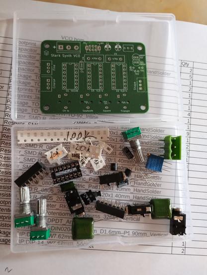
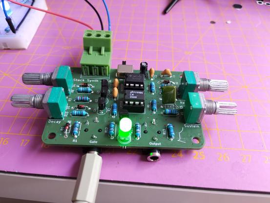
Three new boards for my #StackSynth arrived from @aislerhq yesterday. They are buffer, #ADSR, and #VCO. The VCO is the first with #SMD components on the bottom side. Two resistor values are missing in my SMD collection: 30k and 68k. I already soldered the ADSR and tested it. The buffer will follow tomorrow.
#diysynth #soldering #synthesizer #envelopegenerator

When designing my Educational DIY Synth Thing I always had in mind that I might be able to hook it up to my Korg Volca Modular.

This post looks at the implications and possibilities.

Warning! I strongly recommend using old or second hand equipment for your experiments.  I am not responsible for any damage to expensive instruments!

CHECK YOUR LEVELS AND SIGNALS, DECIDE FOR YOURSELF, AND PLUG THINGS INTO YOUR KORG VOLCA AT YOUR OWN RISK!?

These are the key previous posts for the main concepts used in this project:

If you are new to electronics, see the Getting Started pages.

Korg Volca Modular Signals

According to the manual that comes with the synth, there are the following internal (i.e. patchable) signals:

  • Audio: -3.3V to 3.3V (so 6.6V peak to peak).
  • Unipolar CVs: 0 to 3.3V.
  • Bipolar CVs: -3.3V to 3.3V.
  • Gates and Triggers: 0 or 3.3V.

And of course, any of these signals as an output can be used as an input to another part of the synth.

One additional source of information comes from The Real Volca Modular Specs by Syntherjack where they have observed the following:

  • Some fully modulated audio signals can get to 9V peak to peak.
  • The carrier signal is a clean 4.5V peak to peak triangle wave.
  • The function generator outputs are close to 0 to 3.3V, although the rise-and-fall function (shape/time) trigger appears to get up to 4.5V at times.
  • The sequence gate outputs are 0 to 3.3V, but the pitch output gives a steady CV based on the currently playing note (from a sequence or the keyboard) across the range 0.5V up to around 2.2V. Apparently it follows a 0.5V/oct internal standard.
  • The highest signal observed by Syntherjack was 9.4V peak to peak which implies that all of the Volca’s inputs should be able to take up to that voltage quite happily (otherwise there would be combinations of jumper wires that could fry the Volca!).

The 0.5V/oct comment on the pitch sequencer is interesting. That implies that the internal standard used by the Volca is half of what you’d expect in (say) a Eurorack 1V/oct common setup.

My own Synth Thing uses 1V/oct internally but only has a range of 0 to 3.3V.

So what I have learned? That the triggers and gates should be fine and compatible. That audio may be clipped as the Volca uses +/- 3.3V and I use 0-3.3V. But the Volca’s pitch CV is half that of the Synth Thing.

Volca to Synth Thing Experiments

Volca pitch CV to Synth Thing

The first experiment is to investigate that 0.5V/oct vs 1V/oct thing to see what that sounds like.

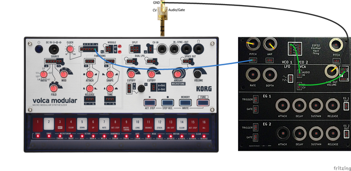
This demonstrates the basic connection from the Volca to the Synth Thing. A key point to note is that the GND must be connected together, but the only way to access that from the Volca is from the CV-In socket, which isn’t ideal.

Once the GND are linked, the Sequencer’s pitch output can be connected to the Synth Thing’s VCO1 pitch input and the pitch pot turned until the pitch matches the note played on the Volca. I tuned it to the lowest note on the keyboard and then could easily hear as it went up an octave that the Synth Thing hadn’t matched the pitch again.

As this is the pitch output for both the sequencer and the Volca’s keyboard, this allows the Volca’s sequencer to drive the Synth Thing too.

Some interesting micro-tonal effects are possible, but if I want pitch parity then I’d need to use some kind of amplifier with a gain of 2 on the output of the Volca to get it to match 1V/oct.

Volca Amplified Pitch CV to Synth Thing

There are lots of circuits around for a simple amplifier with a 2x gain, but perhaps one of the best for this type of application might be a classic non-inverting amplifier op-amp circuit.

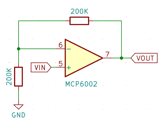
At its simplest it is as follows:

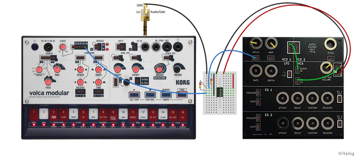
The gain is 1 + R1/R2 so when R1 = R2 that gives a gain of 2. A MCP6002 is a “rail to rail” opamp so it can work essentially up to the power supply. In this case I’ll power it via the 5V supply from the Synth Thing.

Now there are a number of other considerations with a practical, accurate amplifier but for my purposes I’m putting on my “little knowledge is dangerous” hat and just going for it.

I’ve used two 220K resistors, but the accuracy of the resistors isn’t very good. The principle largely works, but I find that if I tune the two synths to the lower note on the Volca, I can’t quite get an accurate octave above. It may be that using variable resistors it might be possible to tune an octave.

There could easily be issues with non-linear tracking of input and output voltage and voltage drops due to impedance issues, but this is where my (limited) knowledge of electronics reaches its limits.

To be honest, I’m not entirely convinced the pitch tracking in the Synth Thing is very accurate anyway! I really ought to do some calibration tests with constant voltages vs frequency.

This is an interesting experiment and something worth exploring a little more in the future, but for now I’m leaving it here.

Volca and Synth Thing ADSR

The final audio output of the Volca can be obtained from the “Space Out” output. Pairing this with the gate from the sequencer allows me to use the Synth Thing’s ADSR envelope generator.

The key thing to watch out for is having the Volca’s release time too short. If it instantly releases then the release phase of the ADSR will seem not to be working.

The other thing to note is that the Volca sequencers gate output always has a break between notes so it isn’t a continuous gate. But playing quickly could easily overtake the release time from the ADSR.

I’m not sure if it is possible to completely bypass the built-in connection between the Volca’s modules, but it might be possible to connect the Source carrier out signal directly into the LPGs and onwards to the output. But that is pretty much bypassing most of what makes the Volca a Korg Volca Modular so I’m not sure why I’d want to do that 🙂

Synth Thing to Volca Experiments

It is probably prudent at this point to repeat the warnings:

  • Check the voltage levels yourself before you attempt to plug anything into your Volca synth and then decide if you’re happy to do so.
  • Do this entirely at your own risk.

I’m daft enough to take the consequences of toasting my Volca but I am not responsible for damage to anyone else’s!

Using the CV/Gate Input

This is by far the easiest, safest, and probably most reliable way to link into a Korg Volca Modular. I covered this before in my Korg Volca Modular Notes, but to recap:

  • The TRS Left (Tip) is an audio or GATE signal input: “clipped to +/-5V and scaled down to +/- 3.3V”.
  • The TRS Right (Ring) is for CV: “1V/octave signal (0 – +6V)”.

This is how to wire up the Synth Thing LFO to the CV input of the Volca.

It uses a stereo 3.5mm TRS to 3.5mm TRS lead – essentially a headphone lead. I’m using my Sparkfun 3.5mm TRS breakout and a solderless breadboard.

The CV signal is available on the lower of the two breakout jumper headers on the Volca. In the patch above it is connected to the control input (middle) of the first LPG.

Other good candidates for patching the CV to are:

  • Source modulation control input.
  • Source fold control input.
  • Space out control input.

You can also get some curious effects by using the “a+bxc” utility module to combine the CV In with one of the internally generated control signals, e.g. the first LPG “+” output.

The CV In can be linked to the Source pitch input too, but there is no way that I’ve found so far of combining a pitch CV input with the keyboard, so the pitch becomes fixed by the CV input only at this point – i.e. it controls the carrier frequency, not the modulator (as far as I can see).

Synth Thing EG controlling the Volca

It is possible to trigger the Synth Thing envelope generator and use the resultant control signal back in the Volca via the CV in as shown below.

The key for this working is to use the Volca’s sequencer GATE output as the GATE and TRIGGER for the Synth Thing’s ADSR envelope generator and then feed the EG output into the Volca’s CV In. The Volca’s CV In is then connected to whatever is to be controlled by the EG – in the above case the first LPG.

Unlike the previous approach that fed the Volca’s output through the Synth Thing’s EG, this now replaces the built-in AHD attack and release EG of the Volca which leads to a much easier to understand set of controls.

Direct connections between Synth Thing and the Volca

Whilst it should be possible to connect the Synth Thing’s patch wires directly into various parts of the Volca, in the end, I decided there wasn’t anything at this point in time that couldn’t be achieved using the official CV In link.

So for the time being, I’ve not experimented further with any direct connections that bypass the official CV In.

Closing Thoughts

I’m intrigued by the 0.5V/oct thing and need to do some further testing of the Synth Thing’s response, but then I was never really happy with how the pitch and amplitude inputs for the VCOs were working. It is on my “todo” list to look into a more efficient way of sample the ESP32’s ADCs.

But I am quite impressed with the possibilities of the CV In on the Volca. Now I’ve explored and noted the basics I’ll have to see what the full “art of the possible” might be.

Kevin

https://diyelectromusic.com/2024/09/01/educational-diy-synth-thing-meets-korg-volca-modular/

#controlVoltage #cv #envelopeGenerator #korg #synthThing #vco #volca

Educational DIY Synth Thing

For a while I’ve wondered if it was possible to find something that could be used to learn about the basics of analog synthesis. This is the first part of a series of posts looking at the pos…

Simple DIY Electronic Music Projects

In the first part I described the concept and basic design parameters I was looking for and then in Part 2 I looked at the detailed electronic design for a board based on the ESP32 WROOM module I have. In this part I go into detail about the code.

  • Part 1 – This introduction and high-level design principles.
  • Part 2 – Detailed design of an ESP32 based PCB.
  • Part 3 – Software design.
  • Part 4 – Mechanical assembly and final use – todo.

Warning! I strongly recommend using old or second hand equipment for your experiments.  I am not responsible for any damage to expensive instruments!

The ESP32 EduMod Hacked Synth Thing

As mentioned in the last part, the principles and code I’m using are taken from these previous posts:

I also now have a built PCB design to make development and testing a lot easier.

Recall the following design choices:

  • The two ESP32 DACs are the output for two envelope generators, each driven by four pots (in standard ADSR configuration), a trigger and a gate signal.
  • There are ESP32 PWM outputs for two VCOs, each with four waveforms (sine, triangle, saw, square) and an analog input (pot or CV) for frequency and amplitude.
  • ESP32 PWM outputs are also used for a LFO with rate and depth analog controls.
  • The ESP32 UART is used for MIDI in.
  • ESP32 digital IO is used for the envelope GATE and TRIGGER signals, although they are level inverted, i.e. they should be read as active LOW.

Othe points to note:

  • There are three “native” analog inputs used for the two VCO pitch and amplitude CVs. All other pots are read via a CD4067 16-way multiplexer.
  • Software will determine how the VCO CVs interact with the potentiometers.
  • The UART RX pin will be used for MIDI and the UART TX pin will be used for one of the PWM outputs, so there will be no serial port (via USB) for diagnostic output.
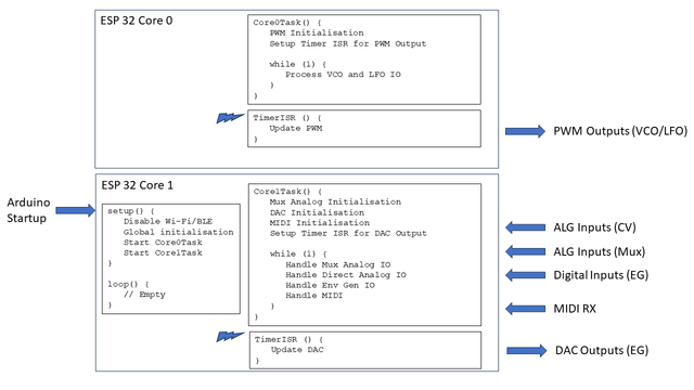
  • The ESP32 is a dual core microprocessor, so the aim is to split the functionality across the two cores.

High Level Design

The tasks will be split as follows:

  • Core 0:
    • Runs the PWM timer at 32,768Hz (although the sample rate will be half this – more on that later).
    • Manages the PWM outputs for the two VCOs and the LFO.
  • Core 1:
    • Runs the EG timer for the DAC at 10,000 Hz.
    • Handles the reading of all the IO: “real” analog values; multiplexed analog values; digital IO.
    • Handles MIDI.

Multicore ESP32 Arduino

Multicore support for the ESP32 on Arduino is provided using FreeRTOS tasks. For a FreeRTOS application, the default Arduino setup()/loop() will run on core 1. However, once tasks have been created to run on the second core, the default loop is no longer used (I believe).

FreeRTOS enables multitasking on a single CPU (core), each with its own internal priority relative to other tasks. But I’m only using it to start a single task on each core. This is achieved using the xTaskCreatePinnedToCore() function. The last parameter specifies which core to use and the 5th parameter indicates the priority – both are set to “1” as there is only a single task on each core.

The Arduino startup code has thus been reduced to the following:

void core0Entry (void *pvParameters);
TaskHandle_t core0Task;
void core1Entry (void *pvParameters);
TaskHandle_t core1Task;

void setup () {
xTaskCreatePinnedToCore(core0Entry, "Core 0 Task", 4096, NULL, 1, &core0Task, 0);
xTaskCreatePinnedToCore(core1Entry, "Core 1 Task", 2048, NULL, 1, &core1Task, 1);
}

void loop () {
// No main loop here
}

void core0Entry (void *pvParameters) {
Task0Setup();

for (;;) {
Task0Loop();
vTaskDelay(1); // Allow FreeRTOS IDLE to maintain watchdog
}
}

void core1Entry (void *pvParameters) {
Task1Setup();

for (;;) {
Task1Loop();
vTaskDelay(1); // Allow FreeRTOS IDLE to maintain watchdog
}
}

I’ve simulated the setup()/loop() pattern in each of the task entry points. One thing I quickly found was that if the tasks run with no release of the processor, then FreeRTOS will fail with a watchdog error.

This is why each task includes a vTaskDelay(1) call to allow FreeRTOS to do whatever it needs to do as part of its “idle” processing.

The other thing to be careful of, which would be the same even in a single core application, is that the timers and their timer interrupt routines also allow some general processing time on each core. This will become important further in the discussion.

Task 0: PWM Generation

The essence of Task 0 is the code from ESP32 and PWM. In order to simplify things I’ve created a basic oscillator class as follows:

class COsc {
public:
COsc ();
~COsc (void);

void Setup (int pwmpin, int wave, bool lfo=false);
void QuadSetup (int sinpin, int sawpin, int tripin, int squpin);
void ScanPWM (void);
void SetFreq (uint16_t freq, uint16_t vol=MAX_VOL);
void SetMVolts (uint32_t mvolts, uint16_t vol=MAX_VOL);
}

Initially the plan was to have one instance per PWM output. The pin and required waveform is configured as part of the call to the Setup() function.

But then I decided it would be more efficient to utilise the fact that the same index and accumulator can be used to read through each of the four wavetables, so created the idea of a “quad” oscillator. This just requires the four PWM pins to be used to be specified as part of the call to QuadSetup() and eliminates several calls into the ScanPWM function for separate oscillators.

There are two ways to set the oscillator’s frequency output. One is to pass in the frequency directly, the other is to pass in a millivolt reading from a potentiometer based on a 1V/oct scaling. The “zero volts” frequency is preset to be 65.406Hz, i.e. C2.

The frequency is derived from the millivolt reading using the following:

void COsc::SetMVolts (uint32_t mvolts, uint16_t vol) {
// Set frequency according to Volt/Oct scaling
// Freq = baseFreq * 2 ^ (voltage)
//
float freq = FREQ_0V * (powf (2.0, ((float)mvolts)/1000.0));
int f = (int)freq;
SetFreq(f, vol);
}

With the default settings this class can be used for both VCO and LFO, but the lowest frequency for the LFO was just 1Hz. Consequently, I’ve added the option to specify a “LFO” setting as part of the single oscillator Setup() function. If enabled, then the oscillator runs 10x slower than default. This allows for frequencies down to 0.1Hz, but does mean that the frequency or millivolt parameters are now treated as being 10 times smaller than their values would imply.

Note when MIDI is added into the mix, I just use the NoteOn message to change the base frequency used for the oscillators.

The ScanPWM() function is designed to be called from the interrupt routine running at the sample rate.

The oscillators are thus created as two Quad oscillators (one per VCO) and two single oscillators for the dual waveforms of the LFO:

#define OSC_VCO1 0
#define OSC_VCO2 1
#define OSC_LFO1 2
#define OSC_LFO2 3
#define NUM_OSC 4
COsc *pOsc[NUM_OSC];
int pwmpins[NUM_OSC][4] = {
{17,18,5,19},
{21,22,1,23},
{16,0,0,0},
{13,0,0,0}
};
int oscwaves[NUM_OSC] = {
OSC_WAVES, // VCO 1 (quad)
OSC_WAVES, // VCO 2 (quad)
OSC_TRI, // LFO
OSC_SAW
};

void oscSetup() {
for (int i=0; i<NUM_OSC; i++) {
pOsc[i] = new COsc();
if (oscwaves[i] == OSC_WAVES) {
// This is a quad oscillator
pOsc[i]->QuadSetup (pwmpins[i][0], pwmpins[i][1], pwmpins[i][2], pwmpins[i][3]);
} else {
// A single oscillator - these are the LFOs
pOsc[i]->Setup (pwmpins[i][0], oscwaves[i], true);
}
}
}

The timer configuration for Task 0 is as follows:

#define TIMER_FREQ 10000000 // 1MHz * 10 (0.1uS)
#define TIMER_RATE 305 // 30.5 uS * 10

Task0Timer = timerBegin(TIMER_FREQ);
timerAttachInterrupt(Task0Timer, &Task0TimerIsr);
timerAlarm(Task0Timer, TIMER_RATE, true, 0);

This generates a timer interrupt running at 32,768Hz from a 10MHz timer

However, servicing 10 PWM outputs means that there is no time remaining once interrupt processing is complete for any other operations. Consequently, I set things up so that the PWM outputs are updated in two blocks of 5, meaning that the effective sample rate for PWM purposes is actually now 16,384Hz:

int toggle0;
void ARDUINO_ISR_ATTR Task0TimerIsr (void) {
toggle0 = !toggle0;
if (toggle0) {
pOsc[OSC_VCO1]->ScanPWM();
pOsc[OSC_LFO1]->ScanPWM();
} else {
pOsc[OSC_VCO2]->ScanPWM();
pOsc[OSC_LFO2]->ScanPWM();
}
}

The main Task 0 Loop just pulls in the analog IO values that have been read as part of the processing of Task 1. These values are then used to set the frequencies of each VCO and the LFO.

Task 0: VCO Control

The VCO potentiometers and CV inputs have to be combined to determine the frequency and amplitude of the PWM signal.

In terms of amplitude, I’ve chosen to use the maximum of the pot or CV input to set the amplitude of VCO 1. Note that VCO 2 has no amplitude input, although with hindsight, I could have included a pot even though I’ve run out of GPIO pins for a CV input.

This means that the pot has to be turned fully “off” for the CV to become significant.

In terms of setting the frequencies, I initially thought about some kind of frequency modulation, which would have been good for linking the two VCOs together, but then decided actually I wanted a more straight forward relationship between pot and CV to allow the use of the LFO or the EGs for pitch. The result is going for a simple summation of the two inputs which gives a 3 octave range (started at C2) for each of the CV and pot, but when combined could give up to a 6 octave spread of frequencies.

When MIDI is enabled, that will set the base frequency for the summation rather than defaulting to C2. This will set the base for both VCOs, so the pots/CVs could be used for a detuning style effect.

Note: Due to the issues with the choice of pins for the inputs, the base level of the CV input for VCO2 is floating at around 300-600mV. The default (unconnected) configuration introduces an element of detuning. If the CV inputs are not wanted, then it is recommended to connect them to GND to eliminate this effect.

The result of taking this approach, combined with the frequency of scanning the inputs, means that if one VCO is used to set the frequency for the other, then it probably won’t track the voltages accurately enough for a smooth modulation. But it does generation quite a wacky “sample and hold” style aliasing effect, which actually I quite like.

I could try to do something about that, but I think in reality this is a use-case where a purely analog VCO can be added via breadboard as part of the experimentation which can be driven from the PWM VCOs – that should enable a number of possibilities for more complex oscillator modulation.

There is also some clipping at higher LFO frequencies if used as the amplitude input. This needs to be investigated to see if that is a bug in the code or handling of the CV somehow.

It is possible that this, and the aliasing of pitch, is a consequence of the frequency of scanning the analog inputs or the speed of the analogRead() function itself – it’s pretty slow. Some investigation is required to experiment with changing the frequency of the reading or rewriting to use the ESP32 API rather than the (slower) Arduino analogRead() function (more on that later).

Task 1: IO Scanning

All the IO is scanned as part of Task 1’s main processing loop. This has to cover the following:

  • Real analog values from the inputs corresponding to the VCO CVs.
  • Multiplexed analog values for all the pots for the VCOs, LFO and two EGs.
  • Digital IO for the EG gates and triggers.

I started off reading the “real” analog IO associated with the VCOs in task 0, but found that it just wasn’t being scanned frequently enough to function in any useful manner. Also, the calls to analogRead() incur some kind of processing overhead that appears to interfere with the timing of the PWM timer interrupt, leaving “blips” in the output.

I started to think about writing a FastAnalogRead() function to use the ESP32 SDK directly rather than the Arduino analogRead() function, but before doing that moved all the IO processing over to Task 1. It turns out that this seems to work adequately so if I’ve not done that at present.

But one consequence of this chain of thought is that I now have two sets of functions performing my own analog IO reading:

  • MuxAnalogRead()
  • FastAnalogRead()

Which both perform in very similar ways. I’ll describe the API for MuxAnalogRead(), but the same principles were used for FastAnalogRead() too.

void MuxSetup(void);
void MuxLoop(bool bVoltageReading=false);
void MuxLoopSingle (uint8_t pot, bool bVoltageReading=false);
uint16_t MuxAnalogRead (uint8_t pot);
uint32_t MuxAnalogReadMilliVolts (uint8_t pot);

The two Loop functions are designed to perform the actual reading from the hardware. Loop will read all known values in a single scan. LoopSingle() will read a single pot.

The functions MuxAnalogRead() and MuxAnalogReadMilliVolts() are used to retrieve the previously read values.

Scanning is performed using either the standard analogRead() or the ESP32 API function analogReadMilliVolts(). This is why a bVoltageReading parameter is required as part of the two Loop functions. It would be possible to calculate one from the other for every reading, but I’ve opted not to do that in order to keep the calculations required as part of a read as minimal as possible.

This allows the scanning of the hardware to happen on one core (in Task 1 in this case) yet be read from the other (Task 0).

Digital IO processing just requires monitoring the trigger and gate inputs for a HIGH->LOW transition and call the appropriate triggerADSR() or gateADSR() functions as required, although there is a bit more logic required to work in the MIDI input.

The actually scanning of IO is split over the different scans of the Task Loop as follows:

#define S_MUX (NUM_MUX_POTS-1)
#define S_FASTIO (S_MUX+1)
#define S_DIGIO (S_FASTIO+1)
#define S_ALGIO (S_DIGIO+1)
#define S_MIDI (S_ALGIO+1)
#define S_LAST (S_MIDI+1)
int taskState;

void Task1Loop(void)
{
if (taskState <= S_MUX) {
// Read each MUX pot in turn
switch (taskState) {
case 5: // VCO 1 CV
case 7: // VCO 2 CV
// These are read in millivolts...
MuxLoopSingle(taskState, true);
break;
default:
// These are read as 12-bit raw 0..4095
MuxLoopSingle(taskState, false);
break;
}
}
else if (taskState == S_FASTIO) {
Task1FastAlgIOLoop();
}
else if (taskState == S_DIGIO) {
Task1DigIOLoop();
}
else if (taskState == S_ALGIO) {
Task1AlgIOLoop();
}
else if (taskState == S_MIDI) {
Task1MIDILoop();
}
else {
taskState = S_LAST;
}
taskState++;
if (taskState >= S_LAST) {
taskState = 0;
}
}

Task 1: Envelope Generation

The core of the envelope generation code is from ESP32 DAC Envelope Generator, but once again the code has been refactored into a class as follows:

class CEnv {
public:
CEnv ();
~CEnv (void);

void setADSR (int eg_a, int eg_d, int eg_s, int eg_r);
uint8_t nextADSR (void);
void triggerADSR (void);
void gateADSR (bool gateOn);
void dumpADSR (void);
}

One change is setting the ADSR parameters in a single call. The values are assumed to be potentiometer readings in the range 0..4095.

Two envelope generators are created by Task 1:

CEnv *pEnv[NUM_ENV];

void envSetup() {
for (int i=0; i<NUM_ENV; i++) {
pEnv[i] = new CEnv();
}
}

The nextADSR() function has to be called for each envelope generator from the timer interrupt routine.

The timer configuration for Task 1 is as follows:

#define TIMER_FREQ 100000 // 100kHz (0.01mS)
#define TIMER_RATE 10 // 0.1mS

Task1Timer = timerBegin(TIMER_FREQ);
timerAttachInterrupt(Task1Timer, &Task1TimerIsr);
timerAlarm(Task1Timer, TIMER_RATE, true, 0);

This generates a 10kHz sample rate for the EGs from a 100kHz timer signal.

Task 1: MIDI

I’m using the standard Arduino MIDI library. There are a couple of points to note however:

  • MIDI will set the TRIGGER and GATE according to the reception of NoteOn and NoteOff messages.
  • I will need to keep track of which note is playing so that overlapping NoteOn/NoteOff messages don’t confuse the GATE handling.
  • As I’m reusing the TX pin as a PWM output, PWM initialisation must happen after MIDI initialisation, otherwise MIDI will assume the use of both RX and TX.
  • Serial MIDI by default implements “software MIDI THRU” so this needs to be disabled using setThruOff().
  • MIDI will set the base frequency used for the VCO controls, so the pot and CV will add to the MIDI frequency.

It isn’t clear what should happen with regards to frequency on NoteOff. Here are some options:

  • Reset back to default base frequency on NoteOff (the “0V” state), but this has the disadvantage that the frequency changes as soon as the gate signal initiates the Release state of the ADSR.
  • Wait until the envelope has finished the Release stage to reset the base frequency. This seems sensible when using the EGs, but has the disadvantage that when just using MIDI to set pitch, it will not revert back immediately on “key up” – it will only revert back when the envelope is complete, which is confusing if the EG is not being used.
  • Don’t reset the base frequency, this means the note will continue on the last used frequency until a new note is played.

I’ve opted not to reset the base frequency on the basis of: if MIDI on/off handling is required, then it will probably be using envelopes anyway. If not, then having only MIDI on setting a sustained frequency sort of makes more sense to me.

Closing Thoughts

The code will continue to evolve as I keep tinkering with it, but the current state can be found in the GitHub repository for the project here: https://github.com/diyelectromusic/ESP32EduModHackThing

There are still a few quirks and things I might continue to investigate and possibly optimise. Specifically:

  • The performance for reading the “real” analog CVs for the VCOs.
  • The frequency handling with respect to MIDI.

But in general I think it is starting to get pretty usable.

Kevin

https://diyelectromusic.wordpress.com/2024/05/26/educational-diy-synth-thing-part-3/

#adsr #define #envelopeGenerator #esp32 #lfo #oscillator #vca #vco
Educational DIY Synth Thing

For a while I’ve wondered if it was possible to find something that could be used to learn about the basics of analog synthesis. This is the first part of a series of posts looking at the pos…

Simple DIY Electronic Music Projects

Following on the back of my ESP32 DAC Envelope Generator and in particular my note at the start that it was essentially the code algorithm and none of the electronics that might make it useful, I started to try to find the simplest possible circuit that Just Might Work as a voltage controlled amplifier (VCA) for demonstration purposes. It turned out to be quite a “rabbit hole”. This post details where I ended up.

But first, just to be clear, I’ll repeat my warning from last time – don’t hook this up to anything else unless you really know what you are doing (unlike me). This is my fumbling around with a little knowledge, largely being “dangerous”, based on random circuits I’ve found online. If that isn’t enough to scare you off, I’m not sure what is…

Warning! I strongly recommend using old or second hand equipment for your experiments.  I am not responsible for any damage to expensive instruments!

If you are new to electronics and microcontrollers, see the Getting Started pages.

Introduction

I’m after a voltage-controlled amplifier (VCA) that can be controlled with my 0-3V3 signal and that could be used to shape an audio signal. This can be thought of as a “black box” with an audio input and output and a control voltage.

But of course there are a large number of considerations if one is to do this properly.

So naturally I threw all that out the window and started searching online for “simple VCA circuit” to see what comes back.

I’m not after any specific quality of VCA, I just want to see the art of the possible with regards to fewest components, simplest design, and useful demonstration of the envelope generator working.

The designs I’ve found can be categorised largely as follows:

  • Opto-electronic based designs – e.g. optoisolators, vacrols or similar.
  • Transistor based designs – often paired with diodes.
  • Op-amp and amplifier based designs – these are starting to get more complex, but seem to produce some pretty usable designs from what I can see.
  • Dedicated chips – e.g. the AS3330, AS3360 and compatible devices.

I’d suggest that I’ve probably listed these in order of simplicity (simplest first) which also seems to be inversely proportional to quality of output (that is, the best is last).

Opto-electronic Based Designs

These had instant appeal to me as they appear to be pretty simple on the face of things. Essentially the control voltage modulates the light emitting side of an optoelectronic device such as an LED; which in turn modulates a light sensing side which controls the level of an audio signal.

Here is one of the simplest designs I found using an optoisolator: https://www.reddit.com/r/synthdiy/comments/lreytp/simple_vca_in_eurorack_format_on_stripboard/
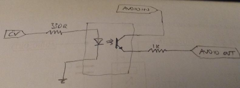
This includes a circuit for an LED to indicate activity, which I wasn’t so bothered about, so I’ve simplified it further to the following:

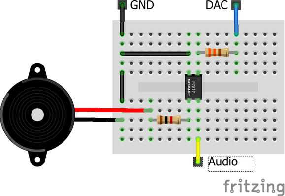
This is about the simplest thing I’ve found and it does kind of work to a degree. I found myself with some cheap optoisolators so used those. The key points to consider for this:

  • The resistor on the CV input has to limit the current through the optoisolator’s LED.
  • The optoisolator’s LED will only start conducting when the CV input reaches the LED’s forward voltage.

I used a PC817 and PC814. The only difference as far as I can see is that the 814 allows for AC operation, incorporating two diodes in the input side.

For both, the forward voltage of the LED is nominally 1.2-1.4V, which is almost half the CV level! This means that attempting to use the envelope generator “as is” significantly reduces the effectiveness of the levels.

There might be a way to bias the input signal, but I’ve not found a simple way in electronics to do this. Ideally, the voltage range for the input would end up in the region of 1.2-4.5V (i.e. up to 3V3+1.2V), but I don’t know how to do that myself for a slow changing voltage like this – at least not without getting more complicated (and probably involving OpAmps) I must admit to being seriously tempted to give this idea a go as suggested by “Chip” on Mastodon as a very crude possibility, but I’m not sure how the DAC would like that…

Another option might be some simple amplification so that the voltage drop across the LED is a smaller fraction of the whole range.

One simple way to avoid the additional electronics is to introduce an offset in the code so that the output of the DAC is in the range 1.2-3.3V, so that is what I’ve done for now and that seems to work pretty well.

On the oscilloscope trace below, I have the output to a 8Ω speaker. We can see that it is ridiculously noisy… but it does work! It sounds a lot better than it looks and there is no filtering or processing going on other than what is shown in the circuit above.

Using a minimum ATTACK_LEVEL of 70 seems to ensure there is little audio leaking, but it is possible to hear where the voltage drops below the forward voltage of the LED – there is a slight blip. In the photo below it is clear to see the non-linearity of the response (top) compared to the control voltage (bottom), especially in the rising ATTACK stage.

The audio in this case is the ESP32 generating a 440Hz tone using the Arduino tone() function, so it is a 0-3V3 square wave being generated.

Most designs using optoelectronics tend to use a VACTROL. This is effectively an LED glued to a LDR in a sealed enclosure. They can be bought or made (apparently VACTROL is a brand name, but that is what everyone calls them).

Here are some circuits and tutorials using a VACTROL as a VCA that look quite interesting and probably worth following up:

  • Kirstian Blastol’s Modular in a Week video “Vactrol VCAs and CV Attenuators”. This video shows how to build your own vactrols using a variety of methods. His “Schematic_Vactrol” is essentially the same circuit as shown above for the optoisolator…
  • Benjie Jiao’s “Passive Vactrol VCA” which is a very similar circuit again, described as a “low pass gate”.
  • “Voltage to resistance” from thesquarewaveparade (search for thesquarewaveparade VtoR.jpg) has a range of increasingly complex, but still relatively straightforward to understand circuits for a voltage-controlled resistance.

But the best discussion on how to make best use of a Vactrol, and hence by inference (by me) probably also an optoisolator can be found here:

I just used exactly the same circuit as for my optoisolator, but the Vactrol I’m using seems to have a larger forward voltage. It is marked VTL5C9, but I’m not sure it’s an “official” Xvive one – but if it is, then the datasheet states a forward voltage of 2.5V which is rather a lot when my control voltage tops out at 3.3V!

To be any use at all, I’ve had to set the minimum ATTACK_LEVEL to 110 which has essentially halved the resolution. But once again, it does work for some definition of “work”.

The longer lead is the anode for the LED side – then I’ve just used it in place of the optoisolator.

Transistor Based Designs

A number of simple VCA designs use a single transistor or a transistor and a diode. I found this one being discussed online so gave that a go:

As far as I can see this is sort of “reversed” in the sense that rather than the control voltage controlling the audio, to me it looks like the audio is controlling the control voltage signal… the end result is still audio only when the control voltage enables it though.

I didn’t have a BC549B transistor, which I believe is a common low-noise NPN transistor, so I used a 2N3904 instead. Note that the pin assignments are different between the two!

One of the advantages of this design appears to be good tracking of the envelope as can be seen below. The actual output level isn’t very high though – the blue scale is 200mV compared to the yellow’s 1V below. I suspect that is a result of attempting to drive the 8Ω speaker directly. I guess this would need to go into some kind of buffer or amplifier stage with some sensible impedance matching at the very least, to be particularly useful.

There is some discussion of this circuit here: https://www.modwiggler.com/forum/viewtopic.php?t=168810. I believe it is only working in the simple case shown above as the audio signal is biased to a 0-3.3V signal rather than a +/- signal.

A bit further down in the linked thread there is an example of how to cope with an unbiased input audio signal by adding a DC bias to the transistor base, so I tried a variant of that as follows:

As I’m using a 3V3 control voltage, I’ve used 680kΩ and 100kΩ to bias the transistor at around 420mV. A coupling capacitor removes any existing DC bias to the audio signal prior to feeding it in.

The final signal at the loudspeaker is pretty low as before, but if I take the output from just before C1 it is looking pretty good to me although we can see the output is still positive only.

Once again, the trick now would be to buffer or set up the load on this signal to preserve it as an actual audio out.

This is pretty crude, but then the discussions implied nothing less. But for a handful of largely passive components, this does seem to show some promise.

For a proper discussion on the workings of transistor based VCAs, I can recommend:

OpAmp Output Buffer

For completeness I briefly experimented with adding a LM358 OpAmp based buffer (or “voltage follower”) circuit as follows:

This is connected instead of the speaker in the previous circuit so the input is coming from the right hand side of the 100nF capacitor, so the input is unbiased. But the OpAmp is running from 5V and there are two resistors on the input which adds a 2.5V bias.

The output is pretty good, but I can see the top of the envelope being clipped in the positive direction. I’m not entirely sure why – I thought powering it from 5V (rather than 3V3) would give enough headroom for a decent signal, but maybe not.

Also my limited electronics knowledge is failing me in understanding how the signal shown above (measured at the collector output for the transistor) becomes the signal shown below (measured after the final capacitor in the buffer circuit).
Once again it is probably something to do with my lack of understanding of output impedance and related topics.

It might work better with a LMV358 rather than a LM358 as apparently the LMV version runs better at lower voltages with output much closer to the power rails (“rail to rail”). It might also be possible to adjust the bias resistors and re-align the signals somehow…

Other Transistor Circuits

I also found a couple of circuits where the control voltage is fed into the base of the transistor to control the audio passing through it in a more “traditional” (or at least, “expected” by me) manner. But I wasn’t really able to get them working, so I didn’t take those any further. One I never actually tried as the LMNC “painfully simple VCA” which is essentially just a diode and transistor.

I also found a circuit describing a “swing VCA” but again my initial experiments didn’t seem to give me anything useful, so I’ve largely ignored those too.

OpAmps and Amplifier Based Designs

In one of the discussions I found talk of a TDA7052A in use as a VCA. It was posted by elektrouwe in the discussion here: https://electro-music.com/forum/topic-63383.html&postorder=asc. Further on in the discussion was another circuit, posted by Hammer.

The original TDA7052 is a 1W mono audio amplifier apparently designed for battery led operations and to be powered by 3-18V. The TDA7052A is an upgrade that adds DC voltage volume control, but I believe the power requirements have increased slightly to requiring a 4.5-18V source.

A good discussion for how to use them can be found here: https://electro-dan.co.uk/electronics/tda7052.aspx.

In particular, note that elektrouwe states:

“TDA7052A has a gain of ~ 56x, which means Vin should be in the 100mV range, otherwise you need an input voltage divider. You MUST use an input coupling cap., because the chip generates an internal DC bias voltage.

Pretty much every other example circuit I’ve seen shows the two outputs (pin 5 and 8) connected directly to a 8Ω loudspeaker, but the design above is only using one of the outputs. The two outputs apparently provide an inverting and non-inverting output option.

Here are some key points that might be relevant to its use as a VCA (from the “TDA7052A/AT: 1 W BTL mono audio amplifier with DC volume control” datasheet, dated July 1994, sometimes braded Philips, sometimes NXP):

  • “The maximum gain of the amplifier is fixed at 35.5 dB.”
  • “The DC volume control stage has a logarithmic control characteristic.”
  • “The total gain can be controlled from 35.5 dB to −44 dB.”
  • “If the DC volume control voltage is below 0.3 V, the device switches to the mute mode.”
  • Positive supply voltage range: 4.5V to 18V.

From the graphs in the datasheet (shown below), the response appears pretty linear when the DC volume control voltage is between 0.4 and 1.2V.

So I think the summary is that to use this as a VCA then the control voltage needs scaling to the 0.4-1.2V range (or thereabouts) and the input signal needs to allow for a maximum 35.5dB gain at the high end of that range. The article I linked to earlier describes the original TDA7052’s 39dB gain as equivalent to a voltage gain of 90 times, so to keep within the 0-5V presumed output range, that would require an input audio signal in the 50-100mV range.

I took an approach that largely used elements of each circuit. From here, we are told:

“The DC volume control is at pin 4. The TDA7052A produces a voltage of around +1.125V at this pin, as well using the current at this pin as a volume reference.”

So I thought the approach of using a PNP transistor to modulate that according to the control voltage was probably the way to go.

To get my CV (which is in the 0-3.3V range) down to 0-1.2V I used a voltage divider of a 2MΩ and 1MΩ resistor dropping the range down to approx 0-1.2V. To keep the audio signal within a sensible range to allow for the full gain, I used another voltage divider, this time using a 1MΩ and 100kΩ resistor dropping my 0-3.3V test signal down to around 0-300mV, which is perhaps still a little high, but it was fine for a test. Any final circuit may have to account for a line-level audio input (probably) so will need to be adjusted accordingly.

Note, from my experiments, the audio input (pin 2) seems to be internally biased at around 2.6V. This was with either a 3V3 VCC or 5V VCC.

So here are the components used:

  • 1x TDA5072A
  • 1x BC557 PNP transistor
  • 1x 1KΩ resistor
  • 2x 1MΩ resistors
  • 1x 2MΩ resistor
  • 2x 1uF electrolytic capacitors
  • 1x 10uF electrolytic capacitor

The circuit is designed for a 0-3.3V CV input and is powered from a 0-5V supply.

And here is my test circuit:

And this seems to work fairly well. In the following trace (I’ve swapped the traces over – blue is now the CV and yellow the output), we can see the effect of both the logarithmic response of the DC volume control of the TDA5072A and possibly some maxing out of the volume when at full (I’m not sure tbh).

But it certainly sounds convincing to me and is perhaps the most promising solution so far.

The LM13700 Transconductance Amplifier

The LM13700 appears to be a massively useful circuit in synthesizer designs! I’ve found it used in at least three designs online and it has a chapter of its own in “Make: Analog Synthesizers” by Ray Wilson.

I’ve not got any at the moment, but here are links to the designs and some further discussions about it:

This will be one to come back to.

Closing Thoughts

This was a bit of a diversion, and really I was after the cheapest, simplest, VCA I could manage to build.

I really like the simplicity of the optoisolator/vactrol approach, and for higher signal voltages I can see that it would work well, but for 0-3.3V signals the non-linearity from the use of the LED is just too great. If I can find a simple way to add ~1.5V to the signal then this would probably work pretty well.

The transistor designs were very encouraging, but I suspect I’d really need a little more electronics knowledge to be able to sensibly use them in a circuit.

The TDA7052 is the easiest for me to understand at present, but I would like to return to the topic if I managed to get hold of some LM13700 equivalent devices at some point.

One group I never mentioned is dedicated VCA/EG chips, like the AS3330/33360 or the CEM2164. Again this is probably a subject to return to at some point, but I’m getting quite well past simple, cheap, lo-fi at that point – these are used in proper modular synth designs.

Just a reminder – none of these circuits have any input protection, there is no buffering, and no thoughts of impedance – they are literally the bare bones that might have a hope of kind of working (if at all). They are just part of me learning how some of these things work.

They are not intended for any real use and certainly not for use with any equipment that isn’t disposable.

Kevin

https://diyelectromusic.wordpress.com/2024/04/20/esp32-dac-envelope-generator-part-2/

#envelopeGenerator #esp32 #lm13700 #optoisolator #tda5072 #vactrol #vca

ESP32 DAC Envelope Generator

I’m continuing my series of experiments with the ESP32 by considering how I might use the twin DACs onboard the WROOM module as a Lo-Fi, 8-bit envelope generator. I’ve not looked at env…

Simple DIY Electronic Music Projects

I’m continuing my series of experiments with the ESP32 by considering how I might use the twin DACs onboard the WROOM module as a Lo-Fi, 8-bit envelope generator. I’ve not looked at envelope generation before, so this is a good excuse to see what it is all about.

Important Note: This is NOT an envelope generator circuit or standalone device at present. It just outputs the waveform to the DAC. There is no electronics here that would make that a usable signal in any kind of controlling manner at present. This is mostly thinking about the code to produce the waveforms.

In short, don’t hook this up to anything else unless you really know what you are doing (unlike me).

Warning! I strongly recommend using old or second hand equipment for your experiments.  I am not responsible for any damage to expensive instruments!

These are the key tutorials for the main concepts used in this project:

If you are new to microcontrollers, see the Getting Started pages.

Parts list

  • ESP32 WROOM DevKit
  • 4x or 8x 10kΩ potentiometers
  • 2x 1kΩ resistors
  • 2x push/toggle switches
  • Breadboard and jumper wires

The Circuit

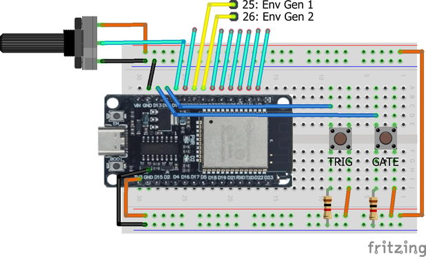
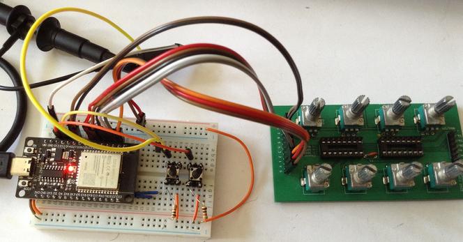
I’ve ended up wiring potentiometers to eight analog inputs, buttons to two digital inputs and put my oscilloscope on each of the DACs to see the output.

The potentiometers are wired in the usual VCC-signal-GND manner (although only one is shown above). The buttons are pulled down as the signals are meant to be active HIGH signals.

The Trigger input is a pulse indicating when a key would be pressed and signifying the start of the envelope generation. When triggered the Attack stage of the envelope will begin immediately followed by the Delay phase. The Gate input is held and meant to indicate while the key is pressed and when it is released. Whilst on, the envelope will remain in the Sustain phase. On removal of the Gate signal the Release stage of the envelope will start.

Note that the plan is for the Trigger to allow retriggering of the envelope at any time and that for removal of the Gate can also happen at any time and start Release. It is also quite possible for there to be several triggers whilst the gate is still active.

It is also possible for the trigger and gate pin to be the same in which case trigger happens on the rising edge along with gate ON and gate OFF will happen on the falling edge.

Here is the full GPIO list for this experiment.

GPIO 25DAC – Envelope 1 outGPIO 26DAC – Envelope 2 outGPIO 12Trigger inputGPIO 13Gate inputGPIO 14Env 1 AttackGPIO 27Env 1 DelayGPIO 33Env 1 SustainGPIO 32Env 1 ReleaseGPIO 35Env 2 AttackGPIO 34Env 2 DelayGPIO 39Env 2 SustainGPIO 36Env 2 Release3V3Pot VCCGNDPot GND

I’ve used the same GATE and TRIGGER signals for both envelope generators, but it would be quite happy with four independent inputs.

Everything here is working with 3V3 logic levels, including the envelope voltages produced.

In the photo below I’ve simplified my wiring by using my Analog IO Board PCB to give me eight potentiometers directly wired into the ESP32.

Envelopes in Mozzi

I’ve already used envelopes in my experiments with ESP32 and Mozzi, but they are applied in software to modulate the amplitude of the Mozzi synthesized output. And really, if using a microcontroller for synthesis this is the natural way to do things.

By way of an example, in Mozzi, envelopes are created on startup, have their parameters changed as part of the control loop, are triggered on and off usually in response to note events, and then have each instantaneous value calculated as part of the audio loop an applied to the sample value.

The essence of their use in Mozzi is as follows:

#include <ADSR.h>

ADSR <CONTROL_RATE, AUDIO_RATE> envelope;

void HandleNoteOn(byte channel, byte note, byte velocity) {
envelope.noteOn();
}

void HandleNoteOff(byte channel, byte note, byte velocity) {
envelope.noteOff();
}

void setup () {
envelope.setADLevels(ADSR_ALVL, ADSR_DLVL);
envelope.setTimes(ADSR_A, ADSR_D, ADSR_S, ADSR_R);
}

void updateControl(){
IF ADSR values have changed THEN
call setADLevels and setTimes again as required
}

AudioOutput_t updateAudio(){
Calculate new 8-bit sample
return MonoOutput::from16Bit(envelope.next() * sample);
}

All that would be required to get this to output just the envelope would be to change the return statement in updateAudio to return the envelope value directly.

AudioOutput_t updateAudio(){
return MonoOutput::from8Bit(envelope.next());
}

There are several more example sketches in Examples->Mozzi->07.Envelopes.

There are several issues with this approach that stop me using this for what I want to do:

  • This only supports one output. I might be able to configure two envelopes and get one output on the “left” channel and one on the “right” channel, which I think then map onto the two DACS…
  • I want to integrate this with some of my ESP32 PWM messing around too, which isn’t easy when Mozzi is determining all the outputs. There is an option to use a user-defined function for the output, but at this point I’m doing a lot more myself anyway…

And anyway, I wanted to work out how an envelope generator could be implemented myself. So I didn’t use Mozzi and got to work on my own implementation.

DIY Envelope Generation using Timers

I had an initial look around at any existing envelope generator implementations for Arduino, having a look at both ADSRduino and the Mozzi ADSR implementation.

In the end I opted for a simpler design of my own, deciding to manage the ADSR as a state machine in code with calculations for how much the envelope level needs to change per tick of a timer. I’m just implementing simple linear updates for each stage.

Setting up the timer is the same as for PWM, but this time I’m using a 100kHz timer with an alarm every 10kHz. This gives me a 0.1mS “tick” which is more than adequate for generating an envelope.

I’ve opted to map the potentiometers onto the ADSR parameters as follows:

  • ADR are mapped using: 1 + potval * 2.
  • S is mapped directly to a value in the 0..255 range, reflecting the 8-bit DAC output.

The time values are in units of 0.1mS so can specify a duration for any of the three stages between 0.1 and 819.1 mS. For pragmatic reasons, when using these values in calculations, I always add 1 so I don’t ever have a divide by zero (which causes the ESP32 to reset).

All values relating to a level are in 8.8 fixed point format, so are essentially 256 times larger than they need to be to give more accuracy in calculations.

The ADSR state machine has the following functionality:

Idle:
Do nothing

Trigger:
Start Attack

Attack:
Increase level to maximum from current level one step at a time
IF level reaches maximum:
Move to Delay

Delay:
Decrease level to sustain level one step at a time
IF level reaches sustain level:
Move to Sustain

Sustain:
Stay at same level while Gate is ON
IF Gate is OFF
Move to Release

Release:
Decrease level down to 0 one step at a time
IF level reaches zero
Move back to Idle

For each stage I maintain a step value, which is how much the level has to change for that specific step. This is calculated as follows:

Num of Steps for this stage = Time of the stage / SAMPLE RATE

Usefully, if I’m measuring the time of the stage in mS then I can use a SAMPLE RATE in kHz and the calculation still works. So the step increment itself can be found by:

Step increment = (Required end level – Starting level) / Num steps

Step increments can be positive or negative of course depending on whether the output is rising or falling.

As already mentioned I’m using 8.8 fixed point arithmetic for the levels. The biggest concern was watching out for automatic wrapping of the 16-bit values whilst performing calculations, so I’ve removed that as a possibility by using signed, 32-bit values for the step increment and stored level.

All the parameters associated with an envelope are stored in a structure:

struct adsrEnv_s {
int32_t env_l;
int32_t steps;
uint16_t attack_ms;
uint16_t attack_l;
uint16_t delay_ms;
uint16_t sustain_l;
uint16_t release_ms;
bool gate;
adsr_t state;
} env[NUM_DAC_PINS];

And there are a number of functions for manipulating the envelope. This is the point where really I ought to be branching over into “proper” C++ and making this an object, but I’ve stuck with C, structures and arrays for now.

The final implementation has a few extra steps in the state machine corresponding to the transitions between stages. This just makes calculating the new step values clearer at the expense of adding an extra timer “tick”‘s worth of processing time to each stage.

Two complications come from how the gate and trigger need to be handled.

The gate has to be checked in each of the stages and if the gate goes to OFF then the state needs to switch over to Release.

The trigger needs to come externally to the main state machine, but in order to ensure I’m not attempting to update variables at the same time that that they are being manipulated by the interrupt-driven state machine function, the trigger just updates the state to a “trigger” state so that on the next tick, the state machine will update itself.

The full set of states recognised now stands as follows (stored roughly in the order they progress through):

// ADSR state machine
enum adsr_t {
adsrIdle=0,
adsrTrigger,
toAttack,
adsrAttack,
toDelay,
adsrDelay,
toSustain,
adsrSustain,
toRelease,
adsrRelease,
adsrReset
};

There is the option of configuring a timing pin so that both the time within the interrupt handler, and the period of the timer can be checked.

There is also a TEST option that manually triggers different stages of the ADSR and dumps the level of one of the envelope generators out to the serial console. This makes tweaking and debugging a bit easier.

The main loop handles the IO updates:

Loop:
FOREACH DAC/EG:
Read Trigger pin
IF Trigger pin goes LOW->HIGH THEN
Trigger ADSR

Read Gate pin
IF Gate pin goes LOW->HIGH THEN
Turn on ADSR Gate
IF Gate pin goes HIGH->LOW THEN
Turn off ADSR Gate

Scan each pot and update ADSR if changed

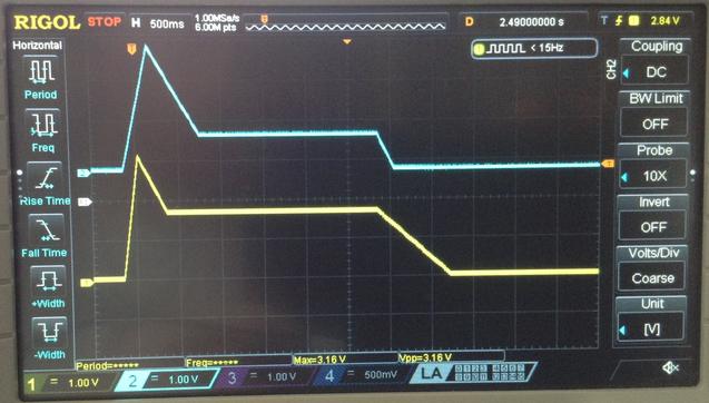
Here is a trace of both envelopes with different ADSR values running off the same trigger and gate:

Find it on GitHub here.

Closing Thoughts

To get any practical use out of this will require some electronics. I can’t just hook the DAC up to something else and expect everything to place nicely, so that is something to consider next.

But for now, although the code is more complex than I original thought, thanks to having to handle the interplay of triggers and gates, it seems to work pretty well.

Kevin

https://diyelectromusic.wordpress.com/2024/04/07/esp32-dac-envelope-generator/

#dac #envelopeGenerator #esp32 #mozzi

DAC — Arduino-ESP32 2.0.14 documentation

After some minor adjustments, I now transferred it onto a soldered #perfboard.
Short demo video: https://makertube.net/w/jiuDuVyXH15G8uXPVBcdno
#soldering #electronics #diysynth #555timer #NE555 #ADSR #envelopegenerator
ADSR demo

PeerTube
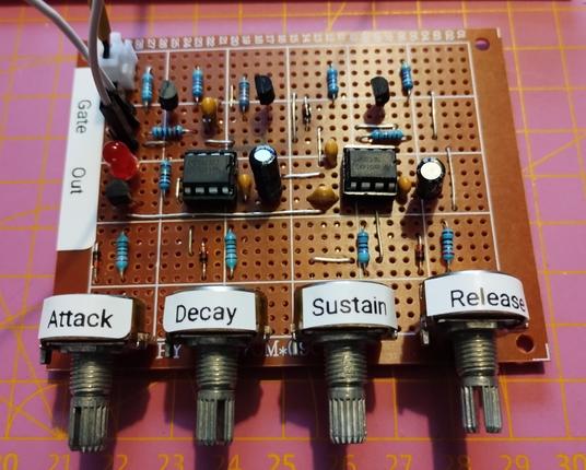
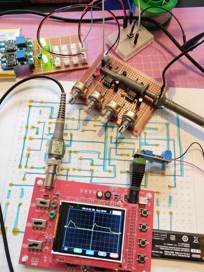
#prototyping an #ADSR #envelope generator on a solderless #breadboard for my #diysynth experiments. I used René Schmitz' design as reference, but using a #bipolar #NE555 instead of the required #CMOS variant, since I didn't have any of those.
I captured the output using my cheap #oscilloscope and used a simple push button.
It seems to work fine, though. I can live with the higher power usage.
Next step: transfer it to a soldered perfboard.
#envelopegenerator #electronics #555 #555timer

#fluffymusic n°304 : Envelope Generator - Hypocrisy

I really enjoy listening to Songs I Hate by @envgen They are really cool !

#envelopeGenerator

https://envelopegenerator.bandcamp.com/track/hypocrisy

Hypocrisy, by Envelope Generator

from the album Songs I Hate