DIY Potentiometer is a Great Teaching Aid
https://fed.brid.gy/r/https://hackaday.com/2026/05/20/diy-potentiometer-is-a-great-teaching-aid/
DIY Potentiometer is a Great Teaching Aid
https://fed.brid.gy/r/https://hackaday.com/2026/05/20/diy-potentiometer-is-a-great-teaching-aid/
#Werbung #Reklame in eigener Sache:
Liebe #vintagehifi Freunde:
Sicherlich kennt Ihr das auch:
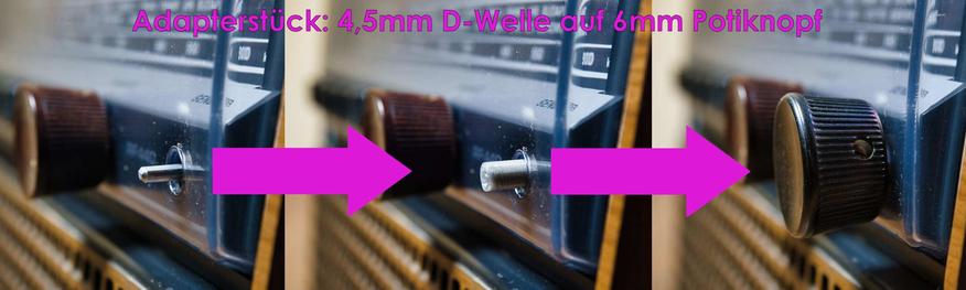
Du hast ein tolles Radio, aber es fehlen die Bedienknöpfe.
Statt dessen ragt nur die nackte Welle aus dem Gerät,
wie auf dem Bild ganz links.
Nun sind Potentiometerköpfe recht leicht zu bekommen, wenn die Welle einen Durchmesser von 6mm hat.
Die Kofferradios haben aber Wellen von 4,5mm mit einer D förmigen Aussparung.
Um dies Problem zu lösen haben wir einen Adapter gezeichnet und gedruckt der es erlaubt auf 4,5mm D Wellen einen Potiknopf mit 6mm (glatt) Innendurchmesser zu montieren.
Auf diese Weie könnt Ihr sogar Potiköpfe von E-Gitarren auf Eure Kofferradios montieren.
Hier könnt Ihr den Adapter kaufen:
https://www.neufeldt-kuhnke.de/shop/Wellenadapter-zur-Montage-von-6mm-innenmass-glatt-Potentiometerkopfen-auf-4-5mm-D-Wellen-Hergestellt-aus-umweltfreundlichem-PLA-Made-in-Germany-p835854813/
#kofferradio #bedienknöpfe #upcycling #restomod #madeingermany #madeinkiel #madeineu #hifi #vintagehifigear #recycling #potikopf
#potentiometer #ersatzteile
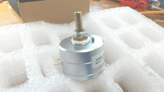
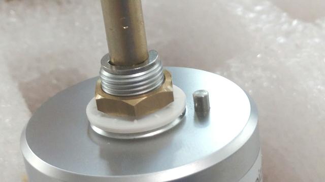
This is one of the precision potentiometers I'll be using in my tube preamp build. They are stepped (like 24 or 27 steps) made with precision film resistors on a small circuit board in there with the stepping mechanism.
I want to get rid of the little nubby sticking up on each pot. I don't have the tools to do this anymore so I'm looking for any suggestions that you might have. I want to get rid of the nubby without damaging the rest of these beautiful things.
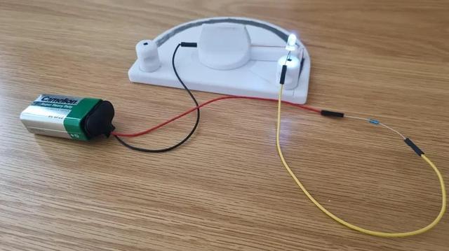
Analog Siren for Psychedelic Soundscapes
https://fed.brid.gy/r/https://hackaday.com/2026/03/21/analog-siren-for-psychedelic-soundscapes/

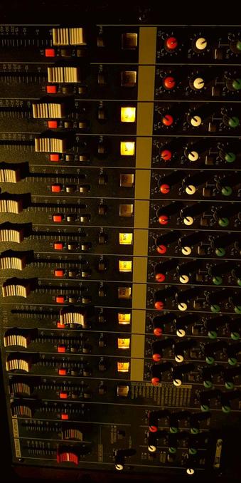
A detailed view of one of my mixing consoles {Yamaha}
Composed in 85F warming light using my Philips Spot Light which I've had since I was a 17 years old teenager!
#Yamaha #JOYO #Console #mixing #faders #potentiometer #AUX #Auxiliary #BUS #gain #Phantom #Power #48V #technology #Audio #music #signal #flow