Since it'll take some time for the PCBs to arrive, I decided to make a #prototype on #perfboard. It works fine, and I can test my programs using it. Turns out an #ATtiny814 is good enough for the task.
The #WS2812B #SMD #LEDs are very bright, though, and reducing brightness also reduces the possible color range.
The different color shadings are not very distinguishable, yet. I might have to adjust the color palette.
#diyelectronics #soldering
I received a few AVR128DA32, which have four times the flash size - now I don't have to keep this in mind while experimenting. Also, I soldered a small #perfboard for the #GameBoyPrinter emulator. I used a few 30AWG flexible silicon wires to route the connections - they fit perfectly through the holes. It's 3cm x 7cm size and I placed the SD slot on the bottom to keep it intact, and the connector for the link cable underneath the display. Now I have to decide which size looks better, 1.3" or 0.9" #oled.
#AVRDA #microcontroller #diyelectronics #GameBoy #soldering #Arduino
One reason for this dev board was to build a #GameBoyPrinter emulator for my #GameBoyCamera. The ATtiny814 just didn't have enough RAM. The NeoGB-Printer is a bit too specialized, I'll adapt the #Arduino GameBoy printer emulator from https://github.com/mofosyne/arduino-gameboy-printer-emulator to my needs. It'll have output on SD card and maybe a TFT status display, the prototype is already wired up. It'll give it a proper board later (might just be a #perfboard).
#AVRDA #prototyping #solderlessbreadboard #diyelectronics #GameBoy
"Bitte ein Bit"
Single ferrite core memory bit, 1.3 mm diameter, 0.4 mm thickness. 0.15mm magnet wire. One vertical wire, one horizontal wire, and one sense wire diagonally.
Magnetizing current roughly 600mA, so 300mA for coincident current addressing.
#electronics
#perfboard
#soldering

When you sketch a circuit with solder and tinned wire, you are already building it !

#79 #SystemsThatMatter #PerfBoard

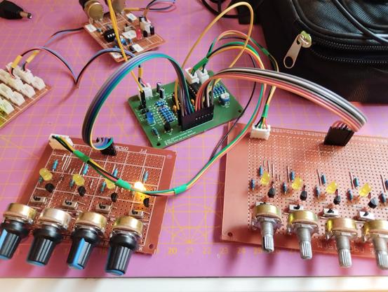
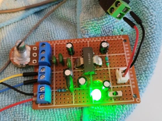
When building electronics project for permanent use - i.e. after testing on a solderless breadboard - you normally go to a #soldered perforated board of some type as a #prototype, or even for very-low-volume production.

There are different types of boards. I dislike "matrix" boards, which are just isolated pads on a grid, i.e. there are no connections between any of them. Some people swear by these; I swear at them.

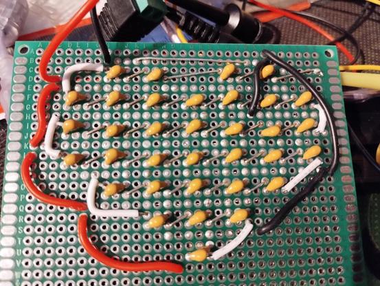
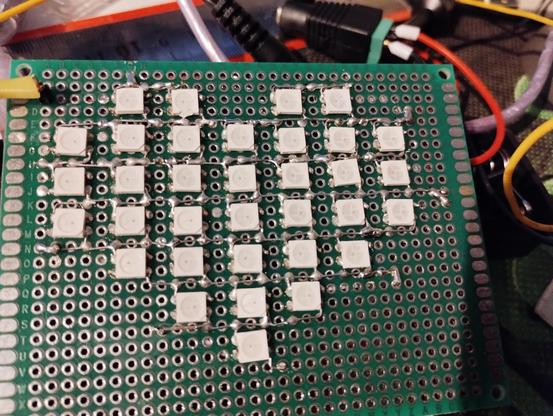
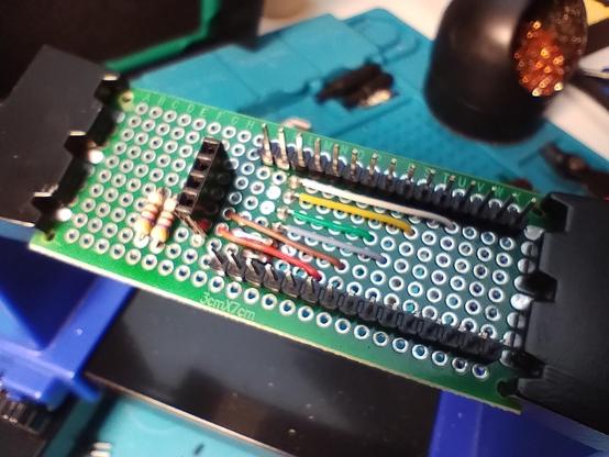
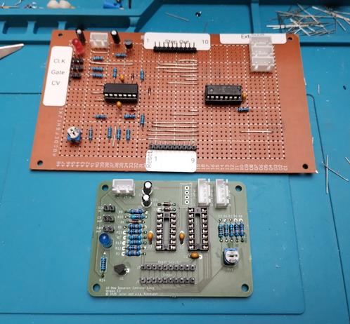
I prefer protoboards that have multiple holes per pad (so you can connect multiple component leads without having to add an explicit wire jumper). If they've also got #busses - sets of pads that run the whole length or width of the board - so much the better!

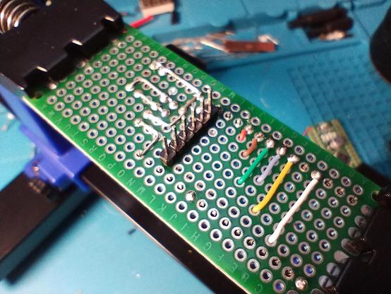
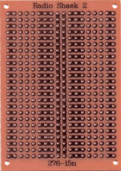
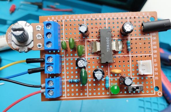
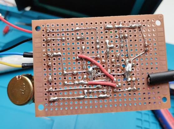
Some are #crap: laminated paper PCBs where the pads lift off the board if you even try to desolder something you added. Row/column labels missing, or (like I found with some recently) that don't line up between the front and back of the board 😆 , or most egregiously, they don't actually show the pad pattern on the front of the board, so you have to keep flipping it to check your parts are correctly placed. One example below.

I have some from "BusBoard Prototype Systems" that I like. The SB4 is a 38 x 24 (912 hole) board that is #snappable into quarters. Two of the quarters have rows that are 4-hole, 2-hole, 4-hole. The other two are 5 2-hole pads. Both types have a single bus running along each of the 2 long sides.

But ...

1/x

#electronics #hobby #ProtoBoard #PerfBoard #MatrixBoard #Chinesium

#soldered the second #PCB that arrived yesterday. This time it's #diysynth related. It's a drop-in replacement for my #perfboard 10 step #sequencer control board. It has identical connectors and was one more test of my PCB design skills and quality of @aislerhq manufacturing. It went really nice and works perfectly in place of the old one.
I only used a bottom ground plane and a different size for the board, so I'll have to redo it again for my final project.
#synthesizer #electronics
I had this old TBA800 IC lying around. So, I designed an audio amplifier circuit. It was fun to solded and works fine. It should support 5W at 16 Ohms load and 24V supply. I only tested it with 12V and 4 Ohms speaker.
The hardest part was soldering the tabs, since they act as heat sink, too.
I used #KiCad for the schematics and layout, although I had to create my own symbol and footprint for the IC. Also had to cut holes for the tabs into the #perfboard.
#electronics #AudioAmp #soldering #diy
A Simple Laser Harp MIDI Instrument

Craig Lindley is a technical author and a prolific maker of things. This simple project was his first attempt to create a laser harp MIDI device. While on vacation, Craig saw a laser harp with only…

Hackaday
Finished building the DrawBridge.
It seems to work, but I need to connect an external 5V power supply, since my laptop doesn't provide enough voltage to power the drive.
Also, this #floppy drive was old, and makes squeaky noises when trying to write. The inserted floppy shows scratch markings, too.
So, I'll need a proper floppy drive.
#Amiga #floppydrive #soldering #perfboard #ArduinoNano #Arduino