Arduino and AY-3-8910 – Part 5

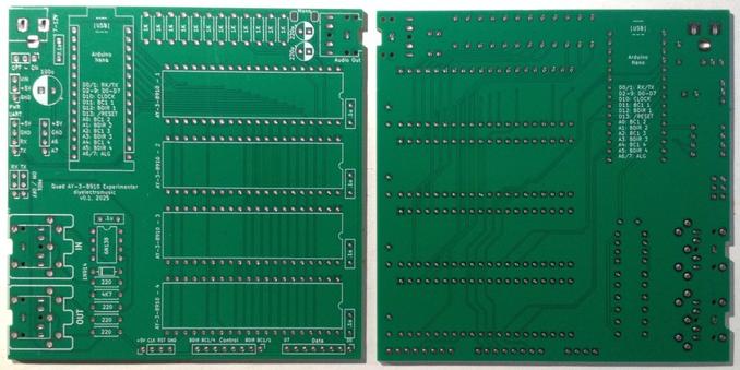
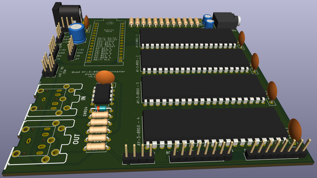
My next bit of messing around with Arduno and AY-3-8910 takes my AY-3-8910 Experimenter PCB Design and adds some simple MIDI reception to create a 12-channel AY-3-8910 tone module.

https://makertube.net/w/hLo4HLYcQkcGvf8N9XzgCS

Warning! I strongly recommend using old or second hand equipment for your experiments.  I am not responsible for any damage to expensive instruments!

These are the key tutorials for the main concepts used in this project:

If you are new to Arduino, see the Getting Started pages.

Parts list

The Code

This is taking a combination of the following previous projects:

I had the option of assigning unique MIDI channels to each of the 12 channels of the quad AY-3-8910s, but instead opted for a system that listens on all MIDI channels but assigns incoming notes to the next free channel.

If there are no spare channels, the notes are ignored.

I’ve included an option to respond to velocity, by translating a MIDI velocity value (0 to 127) into a AY-3-8910 amplitude level (0 to 15). But for now, I’m using it with a fixed velocity.

In order to map a polyphonic note index onto a chip and channel, I use the following:

void ayNoteOn (int chan, int pitch, int vel) {
int ay = chan / 3;
int ch = chan % 3;
aySetFreq (ay, ch, pitch, vel);
}

The aySetFreq() function takes a MIDI nonte number and turns it into a course an fine frequency value for programming into the AY-3-8910.

void aySetFreq (int ay, int ch, int note, int vel) {
int vol = vel >> 3;
uint16_t freq = 0;
if (note != 0) {
freq = pgm_read_word(&Notes[note-NOTE_START]);
}

switch (ch) {
case 0:
ayFastWrite (ay, AY38910Regs::A_TONE_C, freq >> 8);
ayFastWrite (ay, AY38910Regs::A_TONE_F, freq & 0x0FF);
ayFastWrite (ay, AY38910Regs::A_AMP, vol);
break;
}
}

Additional case statements are provided for channels 1 (B) and 2 (C). The Notes array is the list of frequencies calculated for a 1MHz clock using the equation provided in the data sheet:

  • Freq (tone) = Freq (clock) / (16 TP)

Where TP is the 12-bit value placed in the course and fine frequency registers. So turning this around and plugging in the frequencies for MIDI notes, we can figure out the 12-bit values required to be programmed into the registers.

In the end, I cheated and used the table already provided here: https://github.com/Andy4495/AY3891x/blob/main/src/AY3891x_sounds.h

This covers all notes from C0 (MIDI 12) to B8 (MIDI 119).

I should also note that I’ve now removed all of the original AY3891x library and am using my own fast-access routines now tailored for supporting four devices.

As I’m using port IO though, this does mean there is a fair bit of hardcoded assumptions about Arduino PORT usage and GPIO pins.

Find it on GitHub here.

Closing Thoughts

The video shows my, now, go-to test of anything linked to Arduinos and tones – a 12-channel arrangement of the end titles of Star Wars Episode IV – A New Hope.

As the code will select the next free channel for incoming notes, sometimes consecutive notes sound slightly different due, presumably, to differences in the output channels of the devices. Something to look at, at some point.

It would also be useful to have a “multi-track” version where each channel is an independent MIDI channel in its own right, but for now, using OMNI and “next free channel” is fine.

I have to say, when the theme really gets going with those vintage 8-bit tone sounds, I could be sitting back in that 80s Star Wars vector graphics video arcade machine… (although apparently that used several Atari POKEY chips, not AY-3-891x- shame. I wonder if you can get hold of those too…)

“The force will be with you. Always.”

Kevin

#arduinoNano #ay38910 #midi #tone

AY-3-8910 Experimenter PCB Design

Following on from my Arduino and AY-3-8910 experiments, one thing I wanted to do was to try to hook up several AY-3-8910 devices and see if I could stack up the polyphony a little. But that is a lo…

Simple DIY Electronic Music Projects

AY-3-8910 Experimenter PCB Build Guide

Here are the build notes for my AY-3-8910 Experimenter PCB Design.

https://makertube.net/w/fULfpG9LNwpb3iCfavVkAp

Warning! I strongly recommend using old or second hand equipment for your experiments.  I am not responsible for any damage to expensive instruments!

If you are new to electronics and microcontrollers, see the Getting Started pages.

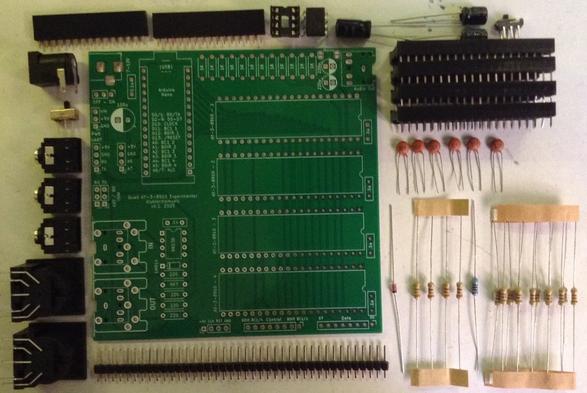
Bill of Materials

  • AY-3-8910 Experimenter PCB (GitHub link below)
  • Arduino Nano
  • Up to 4x AY-3-8910 40-pin DIP devices (see notes here on obtaining devices: Arduino and AY-3-8910)
  • 1x 6N138 optoisolator
  • 1x 1N4148 or 1N914 signal diode
  • Resistors: 4x 220Ω, 1x 4K7, 14x 1K
  • 6x 100nF ceramic capacitors
  • 2x 1uF electrolytic capacitors (the PCB has 220uF on the sinkscreen)
  • 1x 100uF electrolytic capacitor
  • Either: 3x 3.5mm TRS PCB mount sockets
  • Or: 1x 3.5mm TRS PCB mount sockets and 2x 180 DIN PCB mount sockets
  • 1x 2.1mm barrel jack socket
  • 2x 15-way pin header sockets
  • 4x 40-way wide DIP sockets
  • Pin headers
  • Optional: 1x SPDT, 1x DPDT both with 2.54mm pitch connectors
  • Optional: 1x 8-way DIP socket

Build Steps

Taking a typical “low to high” soldering approach, this is the suggested order of assembly:

  • All resistors and diode.
  • DIP and TRS socket(s).
  • Disc capacitors.
  • Switches (if used).
  • Electrolytic capacitors.
  • 15-way pin header sockets.
  • Barrel jack socket.
  • DIN sockets (if used).

It is necessary to add two additional 1K resistors as patch-links on the underside of the board. Details below.

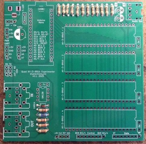
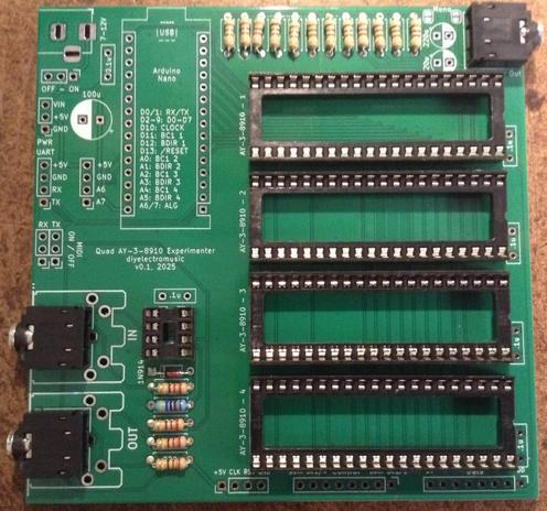
Here are some build photos.

The DIP sockets should go on next before the TRS sockets.

Pin headers and jumpers could be used for the MIDI on/off switch. The power switch could be bypassed with a wire link if not required.

There are a number of optional pin header breakouts: power, UART, additional IO and all the IO for the four AY-3-8910 chips. For this build I’m not populating those.

Errata Fixes

As mentioned in the design notes, two additional resistors must be added to pull the audio outputs to GND as part of the output/mixer circuit. I used two additional 1K resistors.

These can be added to the underside of the board as shown below.

Testing

I recommend performing the general tests described here: PCBs.

Once everything appears electrically good, here is a test application that will play a chord on each of the devices at a different octave. If this works it should be possible to hear all 12 notes in the four chords across four octaves sounding.

Find the code here: https://github.com/diyelectromusic/sdemp/tree/main/src/SDEMP/ArduinoAY38910QuadTest

PCB Errata

As already mentioned there are the following issues with this PCB:

  • The two 220uF capacitors should be replaced with 1uF capacitors.
  • Two additional resistors need to be patched into the audio output circuit.

Enhancements:

  •  None

Find it on GitHub here.

Sample Applications

Here are some applications to get started with:

  •  (on their way)

Closing Thoughts

It took quite a long time to realise the issue with the output channels. For ages, it appeared that the interface to the chip just wasn’t functioning correctly. With hindsight, some kind of register read/write test would have confirmed that a lot earlier.

It was only when going back to the schematics of other designs and recognising that the output was always HIGH did the penny drop that the additional resistor was required. Then there was some experimentation to find something that would work with my board and not cause issues in use.

But it seems like I got there in the end. Now I can get on with doing something a little more interesting MIDI and music wise.

Kevin

#arduinoNano #ay38910 #pcb

Has anyone successfuly uploaded Arduino sketches to the Nano ESP32 using the Upload button in the official IDE?

I can only upload them by putting the board in "flash bootloader" mode, burning the bootloader and then uploading the sketch using the ESPTool programmer, which is pretty convoluted I think

EDIT: I had wrongly set up the udev rules ._.

#Arduino #Nano #ESP32 #ArduinoNano #NanoESP32

Arduino and AY-3-8910 – Part 4

After Part 3 I started to go back and add MIDI, and changed the waveform on the touch of a button, and then started to wonder if I could add envelopes and so on.

And then it occurred to me, I didn’t really need to re-implement my own synthesis library, I could probably write a custom audio output function for Mozzi and get it to use the AY-3-8910 as a 4-bit DAC…

https://makertube.net/w/ast3HQ2a3fCanKy9Pr6qUc

Warning! I strongly recommend using old or second hand equipment for your experiments.  I am not responsible for any damage to expensive instruments!

These are the key tutorials for the main concepts used in this project:

If you are new to Arduino, see the Getting Started pages.

Parts list

  • Arduino Uno.
  • AY-3-8910 chip.
  • Either GadgetReboot’s PCB or patch using solderless breadboard or prototyping boards.
  • 5V compatible MIDI interface.
  • Jumper wires.

Mozzi Custom Audio Output

Mozzi supports a wide range of microcontrollers with a range of different output methods from PWM, built-in DACs, I2S, through to custom output options with DMA or something else.

I’m not going to go over how Mozzi works here, but here are details of how to run with the different audio output modes here: https://sensorium.github.io/Mozzi/learn/output/

The key option for me is MOZZI_OUTPUT_EXTERNAL_CUSTOM. There are a number of configuration options that must be set prior to include the main Mozzi file as follows:

#include "MozziConfigValues.h"
#define MOZZI_AUDIO_MODE MOZZI_OUTPUT_EXTERNAL_CUSTOM
#define MOZZI_AUDIO_BITS 8
#define MOZZI_CONTROL_RATE 64
#define MOZZI_AUDIO_RATE 16384
#define MOZZI_ANALOG_READ MOZZI_ANALOG_READ_NONE
#include <Mozzi.h>
#include <Oscil.h>
#include <tables/cos2048_int8.h>
#include <mozzi_midi.h>
#include <mozzi_fixmath.h>

This sets up the audio synthesis parameters to 8 bit audio with a sample rate of 16384Hz.

Implementing a custom audio output this way requires two functions. One for the audio output and one to tell Mozzi when it is time to call the audio output function.

I would rather have used MOZZI_OUTPUT_EXTERNAL_TIMED which handles the calling at the correct AUDIO_RATE for me, but that relies on the use of the ATMega328’s Timer 1, but in this case Timer 1 is providing the 1MHz clock for the AY-3-3810.

But rather than implementing yet another timing routine, I just used the micros() counter to decide if it was time to generate audio or not.

void audioOutput(const AudioOutput f)
{
int out = MOZZI_AUDIO_BIAS + f.l();
ayOutput(0,out);
}

unsigned long lastmicros;
bool canBufferAudioOutput() {
unsigned long nowmicros = micros();
if (nowmicros > lastmicros+58) {
lastmicros=nowmicros;
return true;
}
return false;
}

To get samples produced at the required 16384Hz sample rate means there needs to be one sample produced 16384 times a second. There thus needs to be a sample every 60uS. If I implement the above function checking for nowmicros > lastmicros + 60 then the resulting sound is slightly flat (in tuning). I’m guessing this is related to the overheads of the function call and logic, so I’ve gone with lastmicros+58 and that sounds pretty good to me.

My ayOutput() routine takes an 8-bit sample and cuts it down to the 4-bits required for a level on the AY-3-8910.

FM Synthesis on the AY-3-8910 (sort of)

I wanted to try the FM synth mode just to see what would happen and thought it would be interesting to switch between the carrier sine wave signal and the modulated signal by pressing the button.

Unfortunately, I just could not get the button logic to work, even though I could see the state of the pin (A5) changing.

Finally after an hour or so of puzzling why such an apparently simple test of logic wasn’t working, I realised what the issue must be. Mozzi, for the AVR microcontrollers, has its own fast ADC routines. It turns out that these were interferrng with using A5 as a digital input pin.

It is fairly easy to override the Mozzi fast ADC though by setting MOZZI_ANALOG_READ to NONE.

The Mozzi code has a carrier and modulator waveform running at audio rate and an index running at the control rate to bring the modulator in and out.

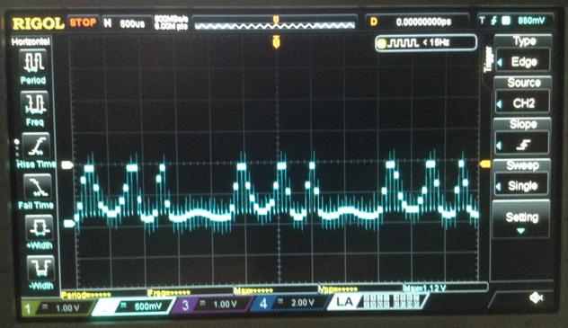
It is just about possible to see the FM modulation on the oscilloscope as shown below.

Of course, the AY-3-8910 isn’t actually doing FM synthesis itself. It is just acting as a 4-bit DAC, but it is still quite fun to see.

Find it on GitHub here.

Closing Thoughts

This is all getting a little pointless really, as there is nothing being done that the Arduino Nano couldn’t do better on its own, but it is a bit of fun to see where this thread ends up.

There are a number of interesting angles now. One of which would be to utilise all three channels. This could provide a form of additive synthesis, it could perform some fixed interval additional oscillators, or it could be used for 3-note polyphony.

Now that Mozzi is running it is also possible to do anything Mozzi can do, and that includes implementing envelope generation.

Kevin

#arduinoNano #ay38910 #include #mozzi

Arduino and AY-3-8910 – Part 3

I suggested in Part 2 that it might be possible to do some simple modulation of the amplitude of the AY-3-8910 channels rather than drive frequencies directly. This is taking a look at the possibilities of some kind of lo-fi direct digital synthesis using that as a basis.

https://makertube.net/w/uCSiBG5RBufGqspoHMYFPt

Warning! I strongly recommend using old or second hand equipment for your experiments.  I am not responsible for any damage to expensive instruments!

These are the key tutorials for the main concepts used in this project:

If you are new to Arduino, see the Getting Started pages.

Parts list

  • Arduino Uno.
  • AY-3-8910 chip.
  • Either GadgetReboot’s PCB or patch using solderless breadboard or prototyping boards.
  • 5V compatible MIDI interface.
  • Jumper wires.

Direct Digital Synthesis on the AY-3-8910

I’ve talked about direct digital synthesis before, so won’t go into full detail again. For more, see Arduino R2R Digital Audio – Part 3 and Arduino PWM Sound Output.

But the top-level idea is to set the level of the signal according to a value in a wavetable. If this value is updated at a useful audio rate then it will be interpreted as sound.

There are some pretty major limitations with attempting to do this on the AY-3-8910 however. The biggest one being that there are only 15 levels for the output on each channel.

So I’ll be working to the following properties:

  • 4-bit resolution for the output.
  • 8-bit wavetable.
  • 8.8 fixed point accumulator to index into the wavetable.
  • 8096 Hz sample rate.

YouTuber https://www.youtube.com/@inazumadenki5588 had a look at this and showed that the AY-3-8910 needs to be set up as follows:

  • Frequency value for the channel should be set to the highest frequency possible.
  • All channels should be disabled.

This is due to comments in the datasheet stating that the only way to fully disable a channel is to have 0 in the amplitude field.

Note: for a 8192 sample rate, that means writing out a sample to the AY-3-8910 registers approximately once every 124uS. With a 256 value wavetable, it takes almost 32 mS to write a complete cycle at the native sample rate, which would be around a 30 Hz output.

I’m not sure what the largest increment that would still give a useful signal might be, but say it was 8 values from the wavetable, then that would make the highest frequency supported around 1kHz. Not great, but certainly audible, so worth a try.

Setting up for DDS

I want a regular, reliable, periodic routine to output the levels from the wavetable, and the usual way to achieve this is using a timer and interrupt. As Timer 1 is already in use to generate the 1MHz clock for the AY-3-8910, I’m going to be configuring Timer 2 as follows:

  • Timer 2 is an 8-bit timer.
  • Use prescalar of 32 which gives a 500kHz clock source (16MHz/32).
  • Use CTC (clear timer on compare) mode.
  • Generate a compare match interrupt.
  • Do not enable any output pins.

The appropriate ATMega328 registers to enable this are:

// COM2A[1:0] = 00 No output
// WGM2[2:0] = 010 CTC mode
// CS2[2:0] = 011 Prescalar=32
ASSR = 0;
TCCR2A = _BV(WGM21);
TCCR2B = _BV(CS21) | _BV(CS20);
TCNT2 = 0;
OCR2A = 60;
TIMSK2 = _BV(OCIE2A);

Although it is worth noting that enabling OC1A can be quite useful for debugging. The following toggles the OC2A output (on D11) every time there is a compare match. The frequency seen on D11 will thus be half the anticipated sample frequency.

pinMode(11, OUTPUT);
TCCR2A |= _BV(COM2A0); // COM2A[1:0] = 01 for OC2A toggle

And this does indeed generate a signal. Here is a trace showing a timing GPIO pin and the AY-3-8910 output.

The problem is that this is meant to be a 440Hz sine wave, and whilst the shape isn’t too bad (it is a little distorted as the amplitude isn’t a true linear shape), the frequency is much nearer 100Hz than 440.

Analysis of Performance

The clue is the other trace, which is a timing pin being toggled every time the Interrupt routine is called. This is showing a 1kHz frequency, which means the IRS is being called with a 2kHz frequency rather than the anticipated 8192Hz. Curiously though I am getting an accurate 4kHz toggle on the timer output pin OC1A indicating the timer is correctly counting with a 8kHz frequency.

No matter how I configured things, the interrupt routine just would not do anything at a faster rate. I had to drop the frequency right down to 2kHz to get the output pin and interrupt routing running together. This means that something in the interrupt routine seems to be taking ~ 450uS to run.

After a fair bit of prodding and probing and checking the ATMega328 datasheet and double checking the register values, I have to conclude that the AY3891x library is just too slow at updating the registers for it to be able to run from the interrupt routine at this speed.

Taking a look at the register write() function in the library, which I need to use to update the channel level, I can see the following is happening:

void AY3891x::write(byte regAddr, byte data) {
latchAddressMode(regAddr);
daPinsOutput(data);
noInterrupts();
mode010to110();
mode110to010();
interrupts();
daPinsInput();
}

void AY3891x::latchAddressMode(byte regAddr) {
mode010to000();
daPinsOutput(_chipAddress | regAddr); // Register address is 4 lsb
mode000to001();
mode001to000();
mode000to010();
}

void AY3891x::daPinsOutput(byte data) {
byte i;

for (i = 0; i < NUM_DA_LINES; i++) {
if (_DA_pin[i] != NO_PIN) pinMode(_DA_pin[i], OUTPUT);
}

for (i = 0; i < NUM_DA_LINES; i++) {
if (_DA_pin[i] != NO_PIN) {
digitalWrite(_DA_pin[i], data & 0x01);
data = data >> 1;
}
}
}

void AY3891x::daPinsInput() {
byte i;

for (i = 0; i < NUM_DA_LINES; i++) {
if (_DA_pin[i] != NO_PIN) pinMode(_DA_pin[i], INPUT);
}
}

And every one of those modeXXXtoYYY() functions is a call to digitalWrite(), so I make that 22 calls to ditigalWrite() in order to write a single register value, plus around 16 calls to pinMode(). There are also 5 loops each looping over 8 values.

One person measured the Arduino Uno digitalWrite() function and concluded that it takes 3.4uS to run, so that is a minimum of 75uS of processing in every run through the interrupt routine just for those calls alone. That doesn’t include the calls and other logic going on. It could easily be more than twice that when everything is taken into account.

Dropping in some temporary pin IO either side of the call to the AY write function itself, and I’m measuring just over 250uS for the register update to happen, and that is just for one channel. This means that anything with a period of that or faster is starving the processor from running at all.

Measuring the Basic Performance

At this point I took a step back and created a free-running test sketch to really see what is going on.

#include "AY3891x.h"

AY3891x psg( 17, 8, 7, 6, 5, 4, 3, 2, 16, 15, 14);

#define AY_CLOCK 9 // D9
void aySetup () {
pinMode(AY_CLOCK, OUTPUT);
digitalWrite(AY_CLOCK, LOW);

TCCR1A = (1 << COM1A0);
TCCR1B = (1 << WGM12) | (1 << CS10);
TCCR1C = 0;
TIMSK1 = 0;
OCR1AH = 0;
OCR1AL = 7; // 16MHz / 8 = 2MHz Counter

psg.begin();

// Output highest frequency on each channel, but set level to 0
// Highest freq = 1000000 / (16 * 1) = 62500
psg.write(AY3891x::ChA_Amplitude, 0);
psg.write(AY3891x::ChA_Tone_Period_Coarse_Reg, 0);
psg.write(AY3891x::ChA_Tone_Period_Fine_Reg, 0);
psg.write(AY3891x::ChB_Amplitude, 0);
psg.write(AY3891x::ChB_Tone_Period_Coarse_Reg, 0);
psg.write(AY3891x::ChB_Tone_Period_Fine_Reg, 0);
psg.write(AY3891x::ChC_Amplitude, 0);
psg.write(AY3891x::ChC_Tone_Period_Coarse_Reg, 0);
psg.write(AY3891x::ChC_Tone_Period_Fine_Reg, 0);

// LOW = channel is in the mix.
// Turn everything off..
psg.write(AY3891x::Enable_Reg, 0xFF);
}

int toggle;
void setup() {
pinMode(11, OUTPUT);
toggle = LOW;
digitalWrite(11, toggle);
aySetup();
}

void loop() {
toggle = !toggle;
digitalWrite(11, toggle);
for (int i=0; i<16; i++) {
psg.write(AY3891x::ChA_Amplitude, i);
}
}

All this is doing is continually writing 0 to 15 to the channel A level register whilst toggling a GPIO pin. Putting an oscilloscope trace on the IO pin and the AY-3-8910 channel A output gives me the following:

This is running with a period of 6.96mS, meaning each cycle of 16 writes takes 3.5mS, giving me almost 220uS per call to the AY write function which seems to align pretty well with what I was seeing before.

And this is generating an audible tone at around 280Hz, so regardless of any timer settings or waveform processing, this is going to be the baseline frequency on which everything else would have to rest, which isn’t great.

Optimising Register Writes

So at this point I have the choice of attempting to write to the AY-3-8910 myself using PORT IO to eliminate the time it takes for all those loops and digitalWrite() calls. Or I could try some alternative libraries.

The library I’m using aims for the most portable compatibility: “This library uses the generic digitalWrite() function instead of direct port manipulation, and should therefore work across most, if not all, processors supported by Arduino, so long as enough I/O pins are available for the interface to the PSG.”

It is a deliberate design choice, but does require all three bus control signals to be used: BDIR, BC1, BC2.

Alternatives are possible with less pin state changes, but much stricter timing requirements. Some options include:

The following are projects that have not used a library, but just done their own thing:

Unfortunately none of these really solves the problem as the PCB I’m using does not neatly map onto IO ports to allow the use of direct PORT IO for the data.

So to improve things whilst using this same PCB will require me to re-write the library myself.

As a test however, it is possible to take the IO pin definitions used with the PCB and write a bespoke, optimised register write routine as follows:

void ayFastWrite (byte reg, byte val) {
// Mode=Addr Latch
digitalWrite(BC1, HIGH);
digitalWrite(BDIR, HIGH);

// Latch address
// NB: Addresses are all in range 0..15 so don't need to
// worry about writing out bits 6,7 - just ensure set to zero
PORTD = (PORTD & 0x03) | ((reg & 0xCF)<<2);
PORTB = (PORTB & 0xFE);
PORTC = (PORTC & 0xF7);

// Mode = Inactive
digitalWrite(BC1, LOW);
digitalWrite(BDIR, LOW);

delayMicroseconds(10);

// Mode = Write
digitalWrite(BC1, LOW);
digitalWrite(BDIR, HIGH);

// Write data
PORTD = (PORTD & 0x03) | ((val & 0xCF)<<2); // Shift bits 0:5 to 2:7
PORTB = (PORTB & 0xFE) | ((val & 0x40)>>6); // Shift bit 6 to 0
PORTC = (PORTC & 0xF7) | ((val & 0x80)>>4); // Shift bit 7 to 3

// Mode = Inactive
digitalWrite(BC1, LOW);
digitalWrite(BDIR, LOW);
}

I’m using the following mapping of data pins to Arduino digital IO pins to PORTS:

DA0-DA5D2-D7PORTD Bits 0-5DA6D8PORT B Bit 0DA7A3/D17PORT C Bit 3

To make this happen I have to ensure that the right bits are set to OUTPUTs and that BC2 is held HIGH prior to using the fastWrite function.

digitalWrite(BC2, HIGH);
DDRD |= 0xFC;
DDRC |= 0x04;
DDRB |= 0x01;

This now improves on that previous 280Hz and gives me 1600Hz performance.

So can I do any better? Well there are still between 6 and 8 calls to digitalWrite going on to handle the control signals…

#define BC1LOW {PORTC &= 0xFE;} // A0 LOW
#define BC1HIGH {PORTC |= 0x01;} // A0 HIGH
#define BC2LOW {PORTC &= 0xFD;} // A1 LOW
#define BC2HIGH {PORTC |= 0x02;} // A1 HIGH
#define BDIRLOW {PORTC &= 0xF7;} // A2 LOW
#define BDIRHIGH {PORTC |= 0x04;} // A2 HIGH

void ayFastWrite (byte reg, byte val) {
// Mode=Addr Latch
BC1HIGH;
BDIRHIGH;

// Latch address
PORTD = (PORTD & 0x03) | ((reg & 0xCF)<<2);
PORTB = (PORTB & 0xFE);
PORTC = (PORTC & 0xF7);

// Need 400nS Min
delayMicroseconds(1);

// Mode = Inactive
BC1LOW;
BDIRLOW;

// Need 100nS settle then 50nS preamble
delayMicroseconds(1);

// Mode = Write
BC1LOW;
BDIRHIGH;

// Write data
PORTD = (PORTD & 0x03) | ((val & 0xCF)<<2); // Shift bits 0:5 to 2:7
PORTB = (PORTB & 0xFE) | ((val & 0x40)>>6); // Shift bit 6 to 0
PORTC = (PORTC & 0xF7) | ((val & 0x80)>>4); // Shift bit 7 to 3

// Need 500nS min
delayMicroseconds(1);

// Mode = Inactive
BC1LOW;
BDIRLOW;

// Need 100nS min
}

The timings come from the AY-3-8910 datasheet:

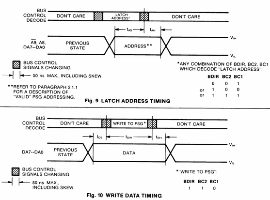
The actual minimum and maximum timings for the various “t” values are given in the preceeding table. Most have a minimum value, but tBD has to be noted: the “associative delay time” is 50nS. This means that any changing of BC1, BC2 and BDIR has to occur within 50nS to be considered part of the same action.

There is no means of having a nano-second delay (well, other than just spinning code), so I’ve just used a delayMicroseconds(1) here and there. This isn’t reliably accurate on an Arduino, but as I’m have delays of around half of that as a maximum it seems to be fine.

This now gives me the following:

This is now supporting a natural “as fast as possible” frequency of around 24kHz, meaning each call to the write function is now around 3uS. That is almost a 100x improvement over using all those pinMode and digitalWrite calls.

The downside of this method:

  • It is ATMega328 specific.
  • It is specific to the pin mappings and PORT usage of this PCB.
  • It does not support reading or other chip operations between the writes.

It is also interesting to see that the traces also show the high frequency oscillation (62.5kHz) that is being modulated regardless of the channel frequency and enable settings.

DDS Part 2

Success! At least with a single channel. This is now playing a pretty well in tune 440Hz A.

Notice how the frequency of the timing pin is now ~4.2kHz meaning that the ISR is now indeed firing at the required 8192 Hz.

Here is a close-up of the output signal. The oscilloscope was struggling to get a clean frequency reading, but this is one time I caught it reading something close! I checked the sound itself with a tuning fork (see video). It is indeed 440Hz.

Find it on GitHub here.

Closing Thoughts

I wanted to get something put together to allow me to drive a DSS wavetable over MIDI, with different waveforms, and so on, but it turned out to be a little more involved getting this far than I anticipated, so I’ll leave it here for now.

But hopefully filling in the gaps won’t take too long and will be the subject of a further post.

Now that I have something that works, I’m actually quite surprised by how well it is working.

Kevin

#arduinoNano #ay38910 #dds #define #directDigitalSynthesis #include #midi

Arduino and AY-3-8910 – Part 2

Following on from my initial experiments in Arduino and AY-3-8910 this post looks at the sound generation capabilities in a little more detail and adds some basic MIDI control.

https://makertube.net/w/3CxNBDKu5Gm6MQzMcLZYz6

Warning! I strongly recommend using old or second hand equipment for your experiments.  I am not responsible for any damage to expensive instruments!

These are the key tutorials for the main concepts used in this project:

If you are new to Arduino, see the Getting Started pages.

Parts list

  • Arduino Uno.
  • AY-3-8910 chip.
  • Either GadgetReboot’s PCB or patch using solderless breadboard or prototyping boards.
  • 5V compatible MIDI interface.
  • Jumper wires.

AY-3-8910 Sound Generation

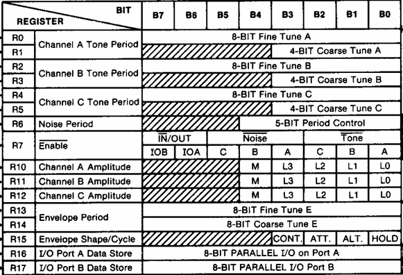
The most basic means of sound generation is to use the three tone generators to generate square waves at a frequency set using the on-chip registers (note in the following data from the datasheet, the R numbers are in octal – so there are 16 registers in total):

I don’t plan to get into the ins-and-outs of how to interface to the chip, instead I’ll link off to some excellent discussions here:

The frequency registers have a 12-bit resolution, spread over two 8-bit registers as shown below.

The datasheet tells us how to calculate the value to write to the register for a specific frequency:

  • Reg Value = System Clock / (16 * frequency)

For a 1MHz clock, the register value is thus 62500 / frequency, so the higher the frequency, the lower the register value. This means that concert A at 440Hz requires the value 62500 / 440 = 142, so:

  • R1 = 142 >> 8;
  • R0 = 142 & 0xFF;

For a 1MHz clock, the range of frequencies goes from 1MHz / 16 to 1 MHz / (16 * 4095) or ~62.5kHz to 15 Hz

The AY3891x library has a set of definitions that already defines the frequencies for each MIDI note from C0 to B8.

The volume for the note is set in another register:

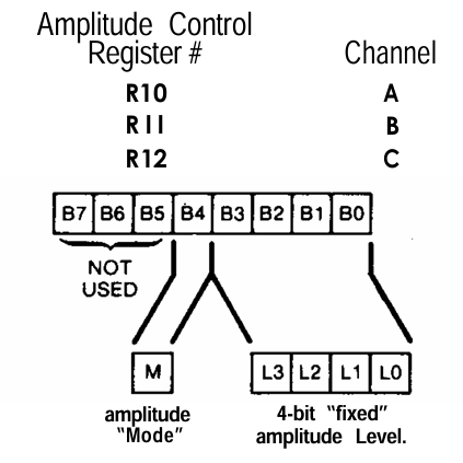
When Mode=0, the amplitude is set by the 4-bit fixed level. When Mode=1, the amplitude is controlled by the built-in envelope generator.

The envelope generator is a “global” setting for all channels, so for finer control, people often wrote their own envelope generator, manipulating the volume levels directly.

The datasheet describes the four parameters required to define an envelope:

Envelopes have a cycle time, which is set by R13 and R14 in a similar way to the frequency. This time the formula is:

  • Reg value = System Clock / (256 * env frequency)

Once again this is split over two registers, but this time supports a full 16-bit value.

There are graphical representations of what the combinations of the envelope bits mean, but I must confess I’m not entirely sure I understand them all and some don’t seem to sound, at least at the frequency I’ve chosen.

The Circuit

I’m reusing the PCB from GadgetReboot from Part 1, but this time I’ve added the button in (it is connected to A5 and GND) and added headers to the UART connection.

Unfortunately the UART only has GND, TX, RX – to use it with one of my Arduino MIDI Interfaces also requires a 5V connection, so I’ve taken that from the SD card header.

The Code

The note-playing code comes from the “AY3891x_EX3_Simple_Tone” example, including the ATmega328 specific code for the 1MHz clock. There is a table of note frequencies already provided for notes C0 through to B8, so it is just a case of mapping these onto MIDI notes C0 (12) through B8 (119).

One thing I wanted was to support simple polyphony using all three channels. But that means deciding what to do when a fourth note comes in – i.e. to ignore it or to replace one of the existing playing notes. I’ve left options for both.

I also wanted to make use of the channel volume too, so it is relatively trivial to map the MIDI 0..127 note velocity values onto the 0..15 levels for the sound generator. This is using the “fixed” level mode mentioned earlier.

But I also wanted the option to play with the envelopes, so I’ve wired in the button and have an option to use that to change between the different envelopes. As I’m not attempting anything particularly complex right now, I just gone with a fixed 10Hz frequency for the envelope generator’s cycle.

It won’t win any prizes for synthesis, but it does work.

Find it on GitHub here.

Closing Thoughts

Fundamentally, without the envelope generation this is the same as a three-channel Arduino tone() function, but at the time that was pretty ground-breaking as it allowed a system to keep playing a tone without having to keep driving it from the CPU.

Add in the noise channel, amplitude control and envelopes and you can start to see why this is also a step up musically too.

But when you get to making custom, per-channel envelopes, or even manipulating the 4-bit level control as a simple DAC or PCM generator, then you can start to see how some of the outstanding chiptunes of the time could be generated.

But even in this simple form there is still a fair bit more that could be done. Some examples might be:

  • Adding a potentiometer to control the envelope frequency. The when used with the triangle envelope this will act as a modulation control.
  • Add MIDI control values for the volume levels, modulation and choice of envelope.
  • Define some specific parameters to create “instruments” which can be selecting using MIDI program change messages.
  • Get the noise generator into the mix and define some percussion “instruments” too.

But what I really want to do is start taking a look at some of the sound drivers that were written that allow some of the chip tunes to come out.

I’m also getting to the point where I want my own PCB with things on it that I want to play with too.

Kevin

#arduinoNano #ay38910 #chiptunes #envelopeGenerator #midi
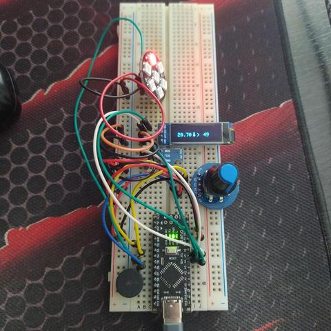
@fast_code_r_us I build this with (more for) my nephew with #arduinonano clone and an #SSD1306 128x32 #oled display.

I used the #U8g2 to display the text and the u8g2_font_unifont_t_weather to display the thermometer icon.

Arduino and AY-3-8910

I’ve had some AY-3-8910 programmable sound generators for a while and planned to do something with them, but they’ve sat in the “to think about” box for a while. But recently getting hold of the WhyEm sound card for the RC2014 has re-awakened my interest.

This is some “first looks” experiments with the AY-3-8910 and an Arduino.

https://makertube.net/w/26yAj7wAzZwCsFoBkJpZs2

Warning! I strongly recommend using old or second hand equipment for your experiments.  I am not responsible for any damage to expensive instruments!

These are the key tutorials for the main concepts used in this project:

If you are new to Arduino, see the Getting Started pages.

Parts list

  • Arduino Uno
  • AY-3-8910 chip
  • Either GadgetReboot’s PCB or patch using solderless breadboard or prototyping boards.

The AY-3-8910 PSG

The AY-3-8910 programmable sound generator is quite an iconic chip of its time. Not as popular maybe as the SID used in the Commodore 64, but still pretty widespread use in 8-bit computers of the time and apparently a number of arcade machines too.

There are a number of “compatible” chips, including the Yamaha YM2149. There is also the AY-3-8912 which is the same as the 8910 but without one of the general purpose IO ports, which take no part in the sound generation.

I’m not going to go into the details of the device itself, for that I’ll refer to the following resources:

The summary of the specification though is as follows:

  • Three square wave output channels.
  • Global AD envelope generator, with a selection of fixed envelopes.
  • Noise generator an option on the channels.
  • Mixer.

There is an 8-bit data register interface to the chip along with three control signals (BDIR, BC1 and BC2).

Sourcing AY-3-8910 Chips

I should point out that it isn’t possible to buy new AY-3-8910 or YM2419 chips these days, so any that can be found online are almost certainly reclaimed from older hardware. These may or may not work reliably, but it will be a bit of a lottery.

There is a lot of discussion about the issue here: http://blog.tynemouthsoftware.co.uk/2023/01/testing-ay-3-8910-ym2149-sound-card-for-rc2014-and-minstrel-4D.html

Some more here: https://maidavale.org/blog/remarked-chips-from-ebay/

This is why RC2014 eventually went with the “Why Emulator” approach: https://rc2014.co.uk/modules/why-em-ulator-sound-module/

My own experience is that you can get them on ebay pretty cheaply. They are often described as “new” but really they will be pulled from older hardware and be cleaned up to look new again.

Usually this means re-tinning the pins with solder, sanding down the original markings, and re-etching the text and logos. I guess they do this to be able to claim “as new”, but personally I’d rather they just let them be sold as reclaimed/recycled. The prices always reflect a reclaimed level of quality to me anyway.

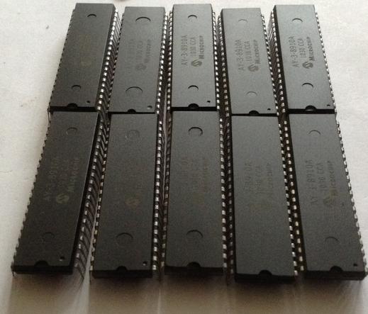
Here is a photo of a recent batch of 10 bought as a pack from the same ebay seller.

Notice how, whilst the text and logos seem to essentially be the same, there are many differences between the actual devices:

  • Depth, position, size of the molding marks.
  • Depth, position, size of the pin 1 marker.
  • Colour of the final finish.
  • They also all have very different under-side markings and appearance (not shown).

I’ve also never seen one yet that doesn’t claim to be a Microchip device, whereas in reality most original devices I suspect would be either Yamaha YM2419 or GI AY-3-8910, so are being re-etched.

It is possible to tell if the device is a YM or AY as they respond slightly differently when the 4-bit registers get written to and read. If the value 31 is written to one of the 4-bit registers then a YM will read back 31 but an AY device will read back 15.

Full details here: http://blog.tynemouthsoftware.co.uk/2023/01/testing-ay-3-8910-ym2149-sound-card-for-rc2014-and-minstrel-4D.html

The Arduino AY3891x library includes a sketch to check and print the result (see below).

Hardware

For once, I’m using someone else’s design for my initial messing about. There is a schematic and some hardware built on a protoboard shown in the Arduino YM3891x library here: https://github.com/Andy4495/AY3891x/tree/main/extras/hardware

But there is a PCB that was designed by GadgetReboot here: https://github.com/GadgetReboot/AY-3-8910. This can be ordered directly from PCBWay and so that is what I’ve used.

The only thing to watch out for, is that D2/D3 are reversed compared to the protoboard hardware. So whilst all other pin definitions in the library examples are fine, D2 and D3 need to be swapped to use them with the PCB.

I also didn’t bother to add the power LED (and R5), the toggle switch or the additional header pins.

The full pinout interface from the Arduino to the AY-3-8910 is as follows:

AY-3-8910ArduinoDA0-DA7D2-D8, A3BC1A0BC2A1BDIRA2CLOCKD9/RESETA4 (not used in the library)

The most critical one from a re-use point of view is the clock as the code uses the ATmega328P hardware Timer 1 to output a 50% duty cycle PWM signal on output OC1A (D9) to generate the 1MHz clock required by the AY-3-8910.

Using a different microcontroller will mean re-writing this part of the code for a suitable replacement timer.

The PCB also has the following Arduino GPIO pin use:

  • D0/D1 – UART pin header
  • D10-D13 – SD card pin header
  • A4 – /RESET of the AY-3-8910 but doesn’t appear to be required to use the library.

The AY-3-8910 is powered from the +5V from the Arduino. VIN for the Arduino is not connected, so USB power is assumed.

The Code

Taking the “AY3891x_EX3_Simple_Tone” example as a starting point, the following line needs updating as shown below:

// Original line
AY3891x psg( 17, 8, 7, 6, 5, 4, 2, 3, 16, 15, 14);

// Required for use with the PCB
AY3891x psg( 17, 8, 7, 6, 5, 4, 3, 2, 16, 15, 14);

This is using the “lesser number of pins” constructor, which assumes that the A8, A9, /RESET and CLOCK pins of the AY-3-8910 are not managed by the library. There is a more complete constructor to define the additional pins if required. There is a good description of how the AY-3-8910 interface works in the main source code: https://github.com/Andy4495/AY3891x/blob/main/src/AY3891x.cpp

I also switched any Serial.begin() statements to use 9600 baud for preference too.

With these changes, the simple tone example just works, as does the “AY3891x_EX8_Check_Orig_or_Clone”, which tells me I have an AY-3-8910 rather than a YM2149.

But what I really wanted was to play one of the tunes from a game I remembered. My first introduction to AY-3-8910 music was the 128K Spectrum version of The Neverending Story. This was one of the two games that came bundled with the original machine, and for someone used to the 48K beeps and boops it was an amazing upgrade.

Unfortunately I don’t seem able at present to find a “YM” file version of that tune to play, so instead I turned to a David Whittaker classic – “Glider Rider”. The “YM Jukebox” GitHub repository has a whole pile of YM files ready to use here: https://github.com/nguillaumin/ym-jukebox/tree/master/data/David%20Whittaker

There are (I believe) two key ways to get “chiptunes” for the AY-3-8910. A YM file is a stream of the register values sent to the chip to direct the sound generation. With one of these files, it is simply a case of turning these values into a C array and it can be included in an Arduino sketch (there are several steps required, see below, but it is all doable).

Another common way to get tunes is an “AY” file. As I understand things these are the actual Z80 assembler instructions required to drive the AY-3-8910 chip, so extracting the required data for use on another system is not so easy. These are really designed to be used on the original systems or via emulation.

To produce an Arduino source code file from a YM file requires the following steps (described here: https://github.com/Andy4495/AY3891x/tree/main/extras/tools):

python decoder.py GliderRider.ym force_interleavedpython bin2c14.py outputfile > chiptunes.h
  • Take the resulting const PROGMEM structure into the “chiptunes.h” file of the “AY3891x_EX6_Chiptunes_Flash” example sketch.

Note that due to the memory limitations of the Arduino Nano, the resulting C structure for the tune will have to be cut-off at around 2000 lines, but be sure to leave the termnating part of the structure:

const byte PROGMEM psg_data[] = {
0x6C,0x07,0x7C,0x07,0x7C,0x07,0x17,0x31,0x0F,0x00,0x00,0x00,0x00,0x20,
0x6C,0x07,0x7C,0x07,0x7C,0x07,0x1F,0x31,0x0D,0x00,0x00,0x00,0x00,0x00,
....
0x7C,0x07,0xBE,0x03,0x58,0x02,0x01,0x31,0x09,0x0E,0x00,0x00,0x00,0x00,
};

If there are build errors, then it might be because the structure is still too long. 2000 lines fits for me using around 97% of the programme memory of the Arduino Nano.

If full (longer) tunes are required, then the PCB has the option to hook up to an SD card and longer files can be stored there.

YM Files

Here is a little more detail about the above process required to get a YM file into C code, mostly for my own reference (the above links all talk about it pretty well tbh).

Step 1: A downloaded YM File is usually actually compressed using LHA. 7Zip can open these files and save the extracted version ready for step 2.

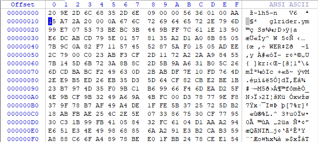
Here is the difference of the start of the files shown using a hex editor. Notice the “-lh5-” header near the start showing that this is a LHA compressed file, and a filename associated with the uncompressed version, in this case glrider.ym.

Uncompressed:

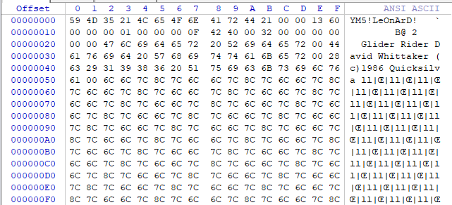
We can now clearly see he header information including the file identifier “YM5!” along with title, author and copyright information in comment fields.

The AU3891x library goes on to explain: “This uncompressed binary file has the audio programming registers stored in a non-interleaved format for more efficient compression. These values now need to be interleaved for more efficient playback.”

We can find more details of the YM file format here, in the words of the creator of the format, Arnaud Carré, directly: https://www.lynn3686.com/ym3456_tidy.html

A music-file is composed of YM2149 registers generated by the
original play-routine for each 50th seconds. As the YM2149 has 14 registers 8 bits each, that means 14 bytes for 1/50 second, so 700 bytes for one second of soundchip.

When I convert an ATARI music, I play the music on the ATARI, and I
store YM2149 registers set each 1/50sec (Vertical Blank time, VBL) in a big file as follow:

VBL1:
store reg0,reg1,reg2,...,reg12,reg13 (14 regs)
VBL2:
store reg0,reg1,reg2,...,reg12,reg13 (14 regs)
...
VBLn:
store reg0,reg1,reg2,...,reg12,reg13 (14 regs)

The problem is that is takes a lot of disk-space. Just count: A 10
minutes song will take 420000 bytes on disk. But don't panic, the music are compressed with LHARC method (using LHA program from Haruyasu Yoshizaki). To reach best compression ratio, I store registers in a different order:

VBL1 reg0, VBL2 reg0, VBL3 reg0 .... VBLn reg0
VBL1 reg1, VBL2 reg1, VBL3 reg1 .... VBLn reg1
...
VBL1 reg14,VBL2 reg14,VBL3 reg14.... VBLn reg14

Hence the “interleaved” format discussed previously. So looking at the file itself, specifically for YM5 it has the following format:

Offset Size Type Comment
0 4 DWORD ID of YM5 format. ('YM5!')
4 8 string[8] Check String ('LeOnArD!')
12 4 DWORD Nb of valid VBL of the file.
16 4 DWORD Song attributes (see below)
20 2 WORD Nb of digi-drum sample (can be 0)
22 4 DWORD YM2149 External frequency in Hz (ex:2000000 for ATARI-ST version, 1000000 for AMSTRAD CPC)
26 2 WORD Player frequency in Hz (Ex: 50Hz for almost player)
28 4 DWORD Vbl number to loop the song. (0 is default)
32 2 WORD Size (in bytes) of futur additinal data. (must be 0 for the moment)

So we can see this playing out from the above file:

00000: 59 4D 35 21 = "YM5!"
00004: 4C 65 4F 6E 41 72 44 21 = "LeOnArD!"
0000C: 00 00 13 60 = Number of frames: 4960
00010: 00 00 00 01 = Attributes:
b0: Set if Interleaved data block.
b1: Set if the digi-drum samples are signed data.
b2: Set if the digidrum is already in ST 4 bits format.
00014: 00 00 = No digidrum samples
00016: 00 0F 42 40 = External frequency 1MHz
0001A: 00 32 = Player frequency 50Hz
0001C: 00 00 00 00 = Number of loops for the song: 0
00020: 00 00

This header is then followed by:

For each digidrum sample:
4 DWORD sample size
nnnn BYTES sample data (8bits per sample)

NT-String Name of the song.
NT-String Name of the author.
NT-String Comments (YM file converter ?!)

All YM2149 registers.

4 DWORD End-File check. ('End!')

Which again we can now see in the uncompressed file:

(no digidrum samples)
00022: 476C6964657220526964657200 = "Glider Rider"
0002E: 4461766964205768697474616B657200 = "David Whittaker"
0003E: 2863293139383620517569636B73696C766100 = "(c)1986 Quicksilva"

00052: 6C6C7C8C... = 4960 values for reg0
013B2: 07070707... = 4960 values for reg1
...
0FC32: 02000000... = 4960 values for reg13
10F92: 00000000... = 2x4960 additional sets of values
13652: 45 6E 64 21 = "End!"

Curiously there seems to be data for 16 registers, which I guess would allow the inclusion of the two GPIO ports as well as the sound generation registers.

So to turn this into a stream of register values to send to the AY-3-8910 at a rate of 50Hz requires take the same “VBL” value for each register in turn and de-interleaving it.

This is the output from the decoder.py file as it processes the above:

Attempting to read file at glrider.ym...
YM5! format file detected based on first four bytes of file...
4960
File is interleaved...
Song title: Glider Rider
Author: David Whittaker
Comments: (c)1986 Quicksilva
Data length is 79360 bytes...
Song length is 4960 frames...
Deinterleaving...
Register 0: 0x6c 01101100
Register 1: 0x07 00000111
Register 2: 0x7c 01111100
Register 3: 0x07 00000111
Register 4: 0x7c 01111100
Register 5: 0x07 00000111
Register 6: 0x17 00010111
Register 7: 0x31 00110001
Register 8: 0x0f 00001111
Register 9: 0x00 00000000
Register 10: 0x00 00000000
Register 11: 0x00 00000000
Register 12: 0x00 00000000
Register 13: 0x20 00100000
==Frame#00000/04959======
Register 0: 0x6c 01101100
Register 1: 0x07 00000111
Register 2: 0x7c 01111100
Register 3: 0x07 00000111
Register 4: 0x7c 01111100
Register 5: 0x07 00000111
Register 6: 0x1f 00011111
Register 7: 0x31 00110001
Register 8: 0x0d 00001101
Register 9: 0x00 00000000
Register 10: 0x00 00000000
Register 11: 0x00 00000000
Register 12: 0x00 00000000
Register 13: 0x00 00000000
==Frame#00001/04959======

...

Register 0: 0x7c 01111100
Register 1: 0x07 00000111
Register 2: 0x54 01010100
Register 3: 0x00 00000000
Register 4: 0x0f 00001111
Register 5: 0x03 00000011
Register 6: 0x01 00000001
Register 7: 0x31 00110001
Register 8: 0x07 00000111
Register 9: 0x0c 00001100
Register 10: 0x0d 00001101
Register 11: 0x00 00000000
Register 12: 0x00 00000000
Register 13: 0x00 00000000
==Frame#04959/04959======

Notice that this is only pulling out the 14 sound generating registers. We can see this in the resultant de-interleaved file.

We can see tha tthe first two values correspond to the first items for reg0 and reg1: 6C and 07 and finish the 14 values with 20 before starting on the new set of 14 register values (again starting with 6C and 07 in this case).

The final step turns the above data stream into a C header file mentioned above.

To play the file thus requires the following algorithm:

Every 50Hz:
Read the next 14 register values from the data
Write all 14 register values out to the AY-3-8910

Closing Thoughts

I’ve really not done very much myself this time. The PCB was from GadgetReboot. The library from Andy4495. The tune data provided by the YM jukebox and all other scripts and bits of the process were available online.

Now I need to decide what I’d like to do with all this.

Kevin

#arduinoNano #ay38910 #chiptunes