@sharplm
A tablets with Windows 98 was a few over the 90s but me as a entrepreneur wanted to make it reallity!
For support a launcher if the case I will had one.
To easy on connecting the net + transfer rightly files to have a flow of really futurstic Handler of the time.
Visual Basic 6
#x86 #Windows98 #tablet #PC #90s #Handler #portable #2000s #Y2K #00 #millenium #Pentium_2 #90s #retro_tech #vintage #rare #futurstic #NeoRetroComputing #Edge_tech of 1999 #birmingham_university #research #GDI
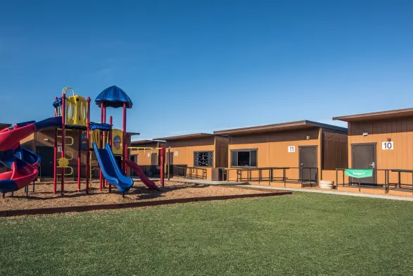
🏩🏩🏩🏩🏩🏩🏩💁🏿♀️*A Leading Provider of Prefabricated Modular & Portable Buildings👉
#Prefabricated #Modular #Portable #Buildings
Modular Buildings for Rent & Sale | Mobile Modular
https://www.mobilemodular.com/
Modular Buildings for Rent & Sale | Mobile Modular
Mobile Modular delivers portable offices, classrooms and modular buildings nationwide. Rent, lease or buy with turnkey delivery. Get a Free Quote.
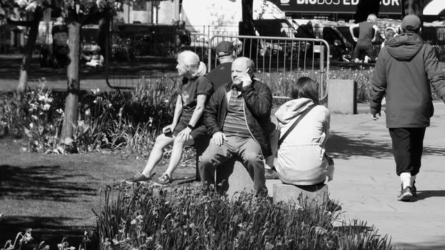
Saint Andrew Square, Spring Afternoon 01
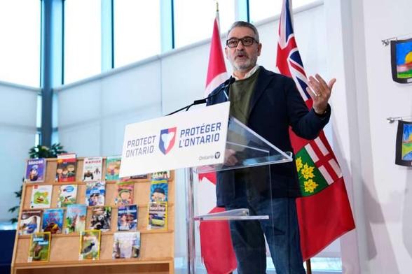
Battle brewing between Ontario education minister, trustee over use of school portable
The Peel District School Board's government-appointed supervisor wrote to trustee and vice chair David Green telling him he must stop using a portable to store items.
#Canada #Education #Brampton #Fordgovernment https://globalnews.ca/news/11844095/ford-government-pdsb-david-green-portable/Battle brewing between Ontario education minister, trustee over use of school portable
The Peel District School Board's government-appointed supervisor wrote to trustee and vice chair David Green telling him he must stop using a portable to store items.
#Canada #Education #Brampton #Fordgovernment https://globalnews.ca/news/11844095/ford-government-pdsb-david-green-portable/