A Road Trip with the POTA Tripod Antenna – with surprises!
A spell of warm, sunny weather and a chance to get out to see the fall colors in early October prompted my wife and I to go on a road trip up to Ontario’s Muskoka region and on to the fabulous Algonquin Park. The park is Canada’s largest and oldest and is the home to thousands of black bears, as well as moose, deer and wolves. Sadly, all the wildlife hid from us on this trip.
Propagation conditions remained uncertain at best, so the third passenger on the truck journey north was my Yaesu FT-891 QROp rig set to an unusually high 35 watts. And the antenna of choice was the 13ft tall vertical based on a tripod that has been the subject of recent posts. Once again, this antenna got the job done, and even revealed some surprises.
Inside Algonquin Park, at Mew Lake campground, I set up to check band conditions. As usual, I started by hunting other activators to see what kind of signal reports I would receive. Bad propagation numbers do not always result in difficulty making contacts. I had considered just leaving the radio in the truck and enjoying the sunshine on the quiet beach by the lake, but after settling into my camp chair I grew restless and within a few minutes I was calling activators and making QSOs.
There are two ways to perform an activation
Calling CQ is the best way; it makes an activator the target for eager hunters and often results in pile-ups. If you know how to handle a pile-up you can complete an activation in short order. But, when conditions are not so good, calling CQ repeatedly and getting no responses can be disheartening. Once I have spotted myself on the POTA website I like to complete at least a basic 10 QSO activation even if it takes a while. Trouble is, when time is limited, other priorities may take precedence and that can result in a busted activation and disappointment. Of course, it is still fun to get on the air out in the Big Blue Sky Shack, but there is another way to have fun and do an activation.
On several occasions I have taken a more relaxed approach and simply hunted other activators until I have completed 10 or more QSOs. This method is a little more difficult because it is necessary to compete with other hunters for each QSO. The advantage, as I see it, is there is no compulsion to complete the minimum 10 QSOs if conditions are bad. I can stop at any point and just consider it a fun day in the park. If I make my 10 contacts I file my logs with POTA and every QSO is automatically a “P2P” (Park-to-Park).
“Hunted activations” are my backup method when time is limited and conditions are bad. On that day in Algonquin Park I chose this method and ended up short of the required minimum of 10 contacts for a valid activation. We had two more days in this mini fall vacation and better conditions were ahead of us, but that day the park had other attractions we wanted to see.
Our overnight accommodation was a “bricks and mortar tent” with breakfast included. Many years ago I canoed into the backcountry inside Algonquin Park every summer and slept in a tent at the edge of several of the park’s many lakes. It was refreshing to get away from the crowds and enjoy the solitude of nature out in the wilderness. In almost complete darkness, at 2:00 AM one night, that solitude was interrupted by a very close encounter with a very large black bear. Fortunately the bear didn’t have me on his supper menu that night. After ransacking the campsite and attempting to claw the food bag down from a tree, it moved on in search of easier meals.
“CB or Ham?” inquired the lady with the Whippet
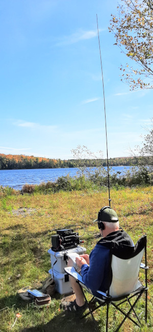
Activating Arrowhead Provincial Park in the October sunshine surrounded by beautiful fall colors.
Leaving the safe, solid, bear-proof accommodation in a nearby town the next morning we entered one of our favorites among Ontario’s parks where we would spend the entire day, with plenty of time for radio. The QTH for the day was Arrowhead Lake Provincial Park (CA-0140), a park I have activated before so I already knew the best location for setting up the radio.
The operating site was at the far end of the lake beside the dog beach. The accompanying picture shows my relaxed operating position. We spent several hours at the dog beach and that included meeting and greeting several dogs (we love dogs).
A couple of ladies came by and one of them asked me: “CB or Ham?”. It is nice when I don’t have to explain ham radio to a visitor. She seemed genuinely surprised though when I explained that I was using Morse Code to contact other hams all over North America. And her pet Whippet was very excited to meet a CW operator in person.
Band conditions had improved since the previous day and the contacts were much easier to obtain. I started out hunting other activators as usual and the contacts just kept adding to my log despite the K-index sitting at an uncomfortable high of 4. The activation wasn’t as fast as if I had called CQ, but time was not pressing so I earned a complete activation, with QSOs to spare, over a period of an hour and a half. Eventually, as the area grew busier, I decided to pack up and head back to the “tent”.
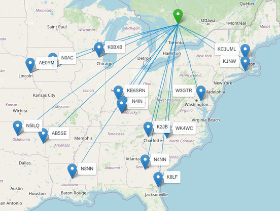
POTA activation at CA-0140 Arrowhead Provincial Park – October 2025
Smoke on the Wahta
The next day we had to head back home, but the route took us via another of my favorite parks – Torrance Barrens Nature Reserve (CA-1669). The “Barrens” is a couple of hours relaxed drive south of Algonquin and the trip took us through the Wahta Mohawk First Nation reserve where tax-free bargains can be found on gasoline and smoking products. My wife and I are not smokers but we are always amused by a sign along the road advertising “Smoke on the Wahta”. Readers who grew up in the same era that we did may recognize the reference to a popular song from the 1970s.
Activating The Barrens
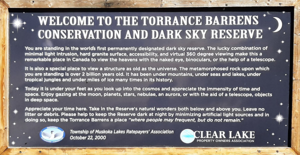
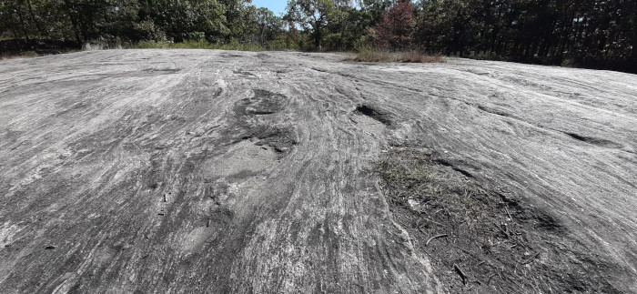
The Barrens is located at the south end of Muskoka and is a popular haunt for astronomers. The topography is characterized by the exposed ancient rock at the southern end of the Canadian Shield.
Exposed 2 Billion years old rock covers much of Torrance Barrens Serene natural beauty elsewhere at Torrance Barrens. Antenna worked fine – despite my failure to deploy the tripod’s top section!
I set up my station on the bare rock near a small lake and once again started hunting other activators to test band conditions. After only four QSOs I switched to CQ mode. Things were going well and in just 27 minutes I completed 15 QSOs. Then suddenly, as I was finishing a QSO with KC5F in North Carolina, my radio shut down. I powered the radio back up again and managed to finish the contact before the radio shut down once again. I checked the voltage of my Bioenno Lithium Iron Phosphate battery and saw the reason why – the voltage was 11.5 volts. I hadn’t recharged it during the trip and it had given up on me. Lithium batteries maintain a fairly constant voltage until they are almost fully discharged. Neglecting to keep them well charged comes with surprises – like a forced QRT.
But that wasn’t the only surprise of the day. As I was packing up my station I noticed that I hadn’t fully erected the antenna. The top tube section of the tripod, which forms part of the radiating element, was not extended. Despite this error the antenna performed very well. I was pleasantly surprised and pleased with the results for the day.
POTA activation at CA-1669 Torrance Barrens Conservation Reserve – October 2025.
Good results despite improperly erected whip and a battery that ran out of charge!
A final word about the radials
I had originally intended to use the linked, tuned radials from my wire version of the POTA PERformer antenna, but there was a problem. Those two raised radials contain links for 17m and 15m. The link for 17m is at 13ft along the 17ft radial wires and the link for the 15m band is at 11ft. Now here’s the rub (as Shakespeare would have said), the radiating element is also 13ft long. Since there is a 4:1 impedance transformer in the feedline the impedance on 17m was out of the tuning range of my LDG Z-11 Pro antenna matching unit.
The solution was to use a set of four 13ft radials laid partly on the ground. Now the LDG Z-11 can easily find a match on all the bands from 20m to 10m. Is 4 radials enough? The feedpoint of the antenna is raised about 3ft/1m above ground so maybe less ground plane is required. Setting antenna physics aside, the prime rule for temporary field expedient antennas is to use the antenna you have and just get on the air.
Winter is fast approaching
Up here in the Great White North life contains 3 absolute certainties: death, taxes and snow! The time for relaxed operating in the sunshine beside a lake is nearly over; now it’s time to get back to planning antennas for operating while shivering in my truck!
Help support HamRadioOutsidetheBox
No “tip-jar”, “buy me a coffee”, Patreon, or Amazon links here. I enjoy my hobby and I enjoy writing about it. If you would like to support this blog please follow/subscribe using the link at the bottom of my home page, or like, comment (links at the bottom of each post), repost or share links to my posts on social media. If you would like to email me directly you will find my email address on my QRZ.com page. Thank you!
The following copyright notice applies to all content on this blog.
This work is licensed under a Creative Commons Attribution-NonCommercial-NoDerivatives 4.0 International License.
#AmateurRadio #Antennas #Counterpoise #CW #OutdoorOps #Portable #POTA

