What’s New in 3D Scanning? All-In-One Scanning is Nice https://hackaday.com/2024/08/27/whats-new-in-3d-scanning-all-in-one-scanning-is-nice/ #HackadayColumns #structuredlight #3dPrinterhacks #Photogrammetry #3DPrintering #3dscanning #3dmodel #Slider #ir

3D Printering: Speed Is So Hot Right Now https://hackaday.com/2024/01/29/3d-printering-speed-is-so-hot-right-now/ #HackadayColumns #3dPrinterhacks #3DPrintering #Featured #tradeoff #klipper #Bambu #prusa #speed
G-code Goes Binary with Proposed New Format
#3dprinterhacks #3dprintering #3dprinting #binary #compression #encoding #gcode #prusaslicer #hackaday
-- Delivered by RssEverything service
G-code Goes Binary with Proposed New Format https://hackaday.com/2023/11/28/g-code-goes-binary-with-proposed-new-format/ #3dPrinterhacks #3DPrintering #compression #PrusaSlicer #3dprinting #encoding #binary #g-code
Make Better 3D Printed Molds, For Thermoforming Plastics https://hackaday.com/2023/09/02/make-better-3d-printed-molds-for-thermoforming-plastics/ #3dPrinterhacks #thermoforming #vacuumforming #3DPrintering #Engineering #hightemp #mold #FDM

Replaced a bunch of shit on my 3d printer, and I think all it needed was some fresh dry filament.
REMOTICON 2021 // Jay Doscher Proves Tinkercad Isn’t Just for Kids
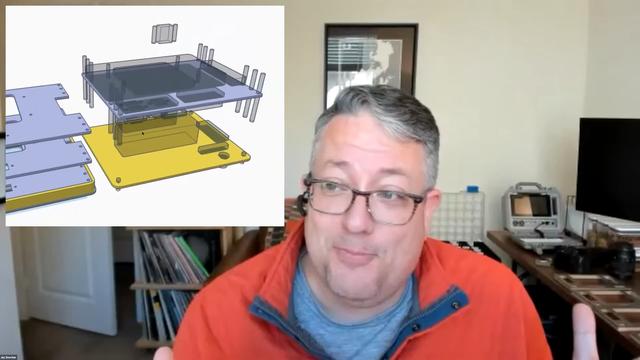
We invited [Jay Doscher] to give us a view into his process designing 3D printed parts for the impressive array of cyberdecks we've covered since 2019.
[Jay] got his start as a maker through woodworking in high school, getting satisfaction from bringing something from idea to reality. After a more recent class in blacksmithing and ax-making showed him what he could do when really focused, his hardware hacking really took off and his line of cyberdecks and other portable computers was born.
If you’ve heard of Tinkercad, you probably think it’s just for kids. While designed as an educational tool, [Jay] found that Autodesk’s younger sibling to the professionally powered (and priced) Fusion 360 had everything needed for making cyberdecks. If you’re willing to work around a few limitations, at the low-low price of free, Tinkercad might be right for you too.
What limitations? To start, Tinkercad is only available in a browser and online. There’s also no guarantee that it will remain free, but [Jay] notes that with its educational focus that is likely to remain the case. There is no library of common components to import while modeling. And, when your model is complete the options for exporting are limited to 2D SVGs and 3D STL, OBJ, and gaming-focused GBL formats. [Jay] has converted those to other formats for laser cutting and the STEP file a machine shop is expecting but admits that it’s something that adds complexity and is an annoyance.
In the talk, [Jay] discusses moving from his initial “cringy” explorations with Tinkercad, to his first cyberdeck, a little history on that term, and the evolution of his craft. It’s mostly a hands-on demo of how to work with Tinkercad, full of tips and tricks for the software itself and implications for 3D printing yourself, assembly, and machining by others.
While quite limited, Tinkercad still allows for boolean operations to join two volumes or the subtraction of one from another. [Jay] does a wonderful job of unpeeling the layers of operations, showing how combinations of “solids” and “holes” generated a complex assembly with pockets, stepped holes for fasteners, and multiple aligned parts for his next cyberdeck. Even if you already have a favorite CAD tool, another approach could expand your mind just like writing software in Strange Programming Languages can.
See the latest from [Jay] on Instagram and his website, or reach out on Discord.
#cons #hackadaycolumns #3dcad #3dprintering #cad #cyberdeck #educational #onlineservice #tinkercad

Ask Hackaday: Are Extruders the Only Feasible Tools for Toolchanging?
Toolchanging in 3D printers is no longer something from the bleeding edge; it's going mainstream. E3D has a high-quality kit for a toolchanger and motion system, our own Joshua Vasquez has shared details about the open-source toolchanging Jubilee design, and just recently Prusa3D formally announced the Prusa XL, which promises toolchanging with up to five different extruders.
A toolchange in progress
It's safe to say toolchanging on 3D printers has stepped to the front, but what comes next? What kind of tools other than extruders make sense on a 3D printer?
First, let's explain what makes separate extruders such fantastic tools. Being able to change extruders on-demand during a print enables things like true multi-material printing. Printing in more than one color or material will no longer be done by pushing different filaments through a single nozzle, which limits a print to materials that extrude under similar conditions and temperatures. Toolchanging means truly being able to print in multiple materials, even if they have different requirements, because each material has its own extruder. That's a clear benefit, but what about tools other than extruders?
3D Printers Have Often Been Modded To Do More
Cutting tools and lasers are two common 3D printer retrofits that seem to be likely candidates for toolchanging, but they are not without their own issues. Lasers require eye protection and ventilation, and cutting tools create troublesome dust and fragments. Nevertheless, over the years we've seen quite a few 3D printers modified into light-duty laser cutters, or converted to CNC engravers. It doesn't end there; we've seen an extruder that embeds copper wire into prints, and even printers turned into through-hole soldering machines.
As clever as these are, some are really just repurposing a 3D printer into something else, and the results have little or nothing to do with the business of extruding plastic to create objects. But others do seem aimed at genuinely enhancing the 3D printing process by adding new capabilities, and could make worthwhile candidates for tools in a toolchanging 3D printer. But which ones make practical sense?
The Best Tools Might Be Ones We Haven't Seen Yet
The most useful tools are likely to be ones that help a 3D printer do its work better, or more efficiently. For example, E3D have made a pretty solid case that a cutting tool as a secondary processing step can add real value to 3D prints under the right conditions.
Another example of enhancing prints is ironing, which uses an extruder's nozzle to smooth out the surface of prints. It looks fantastic when it works, but as that link explains, reliability and results can vary. Perhaps a specialized tool, designed specifically for ironing, could smooth prints more reliably and efficiently than an extruder nozzle? Such a tool might even be useful for embossing prints, as well.
A more ambitious task would be a pick-and-place tool that can drop hardware like nuts or magnets into a print while it's in progress. 3D prints that contain captive hardware would no longer need a human operator involved; a boon for using 3D printers in a manufacturing role.
Of course, the possibilities aren't limitless. A tool will be limited to a certain size and shape, and a 3D printer's frame and construction will also play a part in what is feasible. For example, a cutting tool requires the machine to press the tool into the part being cut, but no such force is required to move an extruder when 3D printing. A machine's capabilities may limit what is possible to do with a given tool. But the enthusiasm with which hackers have pursued things so far makes me suspect that there's much more where all that came from.
Do Tools Besides Extruders Make Sense?
Maybe robust and open toolchanging won't just be bringing multi-material printing to workbenches. Perhaps its real contribution will be the way it continues to enable the kind of enthusiastic experimentation hackers have displayed for modifying 3D printers, and lead to things we haven't even seen yet. In the meantime, extruders seem to be enough to worry about.
What's your experience with toolchanging? Are things like pens, lasers, and cutters on a 3D printer just gimmicks, or can they actually enhance and improve the job of creating useful plastic parts? We're listening, so let us know what you think in the comments.
#askhackaday #featured #hackadaycolumns #3dprintering #3dprinters #extruder #toolchanging
3D Printering: Corrugated Plastic for Cheaper & Easier Enclosures
Clear acrylic panels have long been a mainstay of 3D printer enclosure designs, but they can also add significant cost in terms of money, shipping, weight, and hassle. An alternative material worth looking at is corrugated plastic (also known by its trade name coroplast ) which is cheap, light, an excellent insulator, and easy to work with. Many enclosure designs can be refitted to use it instead of acrylic, so let's take a closer look at what it has to offer.
What's Wrong With Acrylic?
It's not just the purchase price that makes acrylic a spendy option. Acrylic is fairly heavy, and shipping pieces the size of enclosure panels can be expensive. Also, cutting acrylic without special tools can be a challenge because it cracks easily if mishandled. Acrylic cuts beautifully in a laser cutter, but most laser cutters accessible to a hobbyist are not big enough to make enclosure-sized panels. If you are stuck with needing to cut acrylic by hand, here are some tips on how to get by with the tools you have.
It is best to source acrylic from a local shop that can also cut it to size with the right tools for a reasonable price, but it is still far from being a cheap material. There's another option: corrugated plastic has quite a few properties that make it worth considering, especially for a hobbyist.
What's Good About Corrugated Plastic?
Most of us know corrugated plastic as the stuff lawn signs are made of. Using it in enclosure design isn't a new idea (here's a printer enclosure made entirely from it, and here is a CNC mill enclosure using it as well) but instead of making an entire enclosure out of it, it can make more sense to use it only as a panel material. There is no need to design a new enclosure from scratch. One can use an existing design and swap the acrylic panels for corrugated plastic ones.
Corrugated plastic, also known as Coroplast.
Corrugated plastic offers quite a few advantages:
- It is a fraction of the cost of acrylic.
- It is an excellent insulator.
- It is lightweight.
- Easily cuts with a sharp blade.
- Available in fire retardant versions if needed.
- Can be bent or folded along the corrugation, with or without scoring it first.
It can be easier to source than acrylic sheets, and is certainly much easier to work with. Any sign shop or plastics supplier likely has it on hand in a variety of colors.
There are a few disadvantages, however.
- A standard thickness is 4 mm. Acrylic, however, is commonly used in 3 mm (or 1/8″) thickness.
- It is not transparent (but windows can be cut easily.)
- It is not fireproof. Like acrylic, it can burn if it gets hot enough. But compared to other plastics, combustion doesn't spew a toxic mess, and is easily extinguished.
Corrugated plastic material being 4 mm thick instead of 3 mm means it is not necessarily a drop-in replacement for acrylic in existing designs. But not every enclosure is constrained by panel thickness.
Using Corrugated Plastic in Enclosures
The two easiest ways to use this material are: create an enclosure by adding panels to an existing structure, or use an existing design but replace the acrylic with corrugated plastic. Below are examples of both.
Make an Enclosure From an Existing Structure
Here is an enclosure I built into a metal IKEA BROR shelving unit, and it easily houses a Prusa Mini 3D printer. The BROR is made from angled metal pieces that contain regularly spaced holes. This makes it very convenient to turn a shelf section into an enclosure just by mounting a few side panels; the regular shelf surfaces provide a top and bottom.
Not only do corrugated plastic panels fit easily behind the angled metal posts, but a few short screws through the convenient holes is all it takes to fully secure them. Windows can be made by cutting a hole, and gluing or taping a clear plastic sheet to one or both sides. CA glue and most other adhesives work fine on corrugated plastic.
The only inconvenience I encountered was when it came to fashioning a door for the front. Instead of making cabinet-style doors with hinges, I took advantage of the lightweight nature of the material to create a simple removable cover. The shelf frame is steel, so I glued several strong magnets into a separate sheet to create a magnetically-attached removable front cover. I can close the front up completely, or leave a gap for airflow as needed. The result is simple, attractive, and cost very little apart from the shelf itself.
Replace the Acrylic in an Existing Enclosure Design
The only problem with refitting an existing enclosure designed for 3 mm acrylic sheets is that 4 mm corrugated plastic may not fit because they are slightly thicker. While it's always possible to simply cut and peel away material until it fits, for best results, panel-retaining parts should be redesigned to accommodate the thicker material.
For example, I like the Prusa V2 LACK enclosure design and its 3D-printed parts, but the next time I build one I will use corrugated plastic panels instead of acrylic. In preparation for this, I have redesigned the necessary parts to accept 4 mm thick material.
Fortunately, Prusa provides not only STL files for their design, but also the CAD files. While it is possible to modify parts that exist only as STL files, in general having access to CAD format files makes this kind of task much easier.
An Under-Represented Material
For 3D printers, enclosure design is still a problem that isn't entirely solved. "Soft" enclosure options like photo tents or fabric grow boxes meant for plants are an option for the cost-conscious, but there are also ways to reduce the cost of more traditional designs. Corrugated plastic offers a lot of advantages in that regard.
The idea of using corrugated plastic in enclosures isn't new, but it does seem under-represented. Do you know of enclosures that make effective or particularly clever use of it, or do you have any tips of your own? We definitely want to hear about it, so share your thoughts in the comments.
#3dprinterhacks #featured #hackadaycolumns #3dprintering #cnc #coroplast #corrugatedplastic #enclosure
3D Printering: Is Hassle-Free Bed Leveling Finally Here?
3D printers have come a long way over the past several years, but the process of bed leveling remains a pain point. Let's take a look at the different ways the problem has been tackled, and whether recent developments have succeeded in automating away the hassle.
Anycubic Vyper, with an auto-leveling feature we decided to take a closer look at.
Bed leveling and first layer calibration tends to trip up novices because getting it right requires experience and judgment calls, and getting it wrong means failed prints. These are things 3D printer operators learn to handle with time and experience, but they are still largely manual processes that are often discussed in ways that sound more like an art than anything else. Little wonder that there have been plenty of attempts to simplify the whole process.
Some consumer 3D printers are taking a new approach to bed leveling and first layer calibration, and one of those printers is the Anycubic Vyper, which offers a one-touch solution for novices and experienced users alike. We accepted Anycubic's offer of a sample printer specifically to examine this new leveling approach, so let's take a look at the latest in trying to automate away the sometimes stubborn task of 3D printer bed leveling.
Why is Bed Leveling an Issue?
In 3D printer terms, bed leveling (or simply "leveling") is a broad term for a process whose end result is getting the first layer of a print deposited optimally onto the build platform. A good first layer is the foundation of a successful print.
To accomplish this, the nozzle needs to remain a constant distance from the build platform across its whole range of movement. If the nozzle is too close to the bed in some places, but too far away in others, that leads to poor quality and failures. Adjusting the printer's bed until it is parallel to the nozzle's range of motion is called leveling. (Machinists would correctly call the process tramming, because nothing actually has to be perpendicular to the earth's gravitational field.)
The extruder in the process of laying down a first layer.
The next step is first layer calibration. This adjusts the Z-axis offset, or the distance between the tip of the nozzle and the surface of the build platform. There needs to be just enough space for the critical first layer of plastic to be deposited evenly, in a uniform thickness, and pressed into the build surface well enough to remain stuck during printing.
Complicating this is the fact that no build platform is perfectly flat. When fractions of a millimeter count, even small imperfections cause problems. High spots or low spots in a build platform are problems because no amount of tilting the print bed will adjust them away. This is one of the reasons leveling problems have persisted over time.
No individual part of bed leveling is particularly complicated, but the many interconnected factors can make it a complex, fiddly task. It's no surprise that people have tried different ways to make the whole process as easy and repeatable as possible.
Some Attempted Solutions
Rafts (a type of sacrificial build platform) were an early method of dealing with bed imperfections, but most solutions now revolve around mesh leveling.
Mesh leveling is a method of compensating for an imperfect print bed in software, but it requires a way to measure the build platform. By taking measurements with a sensor, a software model representing the build surface, and its imperfections, can be created. This model modifies the path of the print head as it lays down the critical first layer, adjusting for an imperfect surface by attempting to follow those imperfections, instead of moving as though they don't exist.
One way to accomplish mesh leveling is by using an inductive sensor to sense the build platform without touching it. Prusa printers use this method to take measurements in a 3 x 3, or optionally 7 x 7, grid before every print. Manually determining an appropriate Z-axis offset for a particular build sheet is still up to the user.
Another option is a physical probe. The BLTouch, for example, is a popular sensor that comes into physical contact with the build platform. Its success as an aftermarket add-on, as well as how often it has been copied, is a good indicator of how much bed leveling remains a pain point for 3D printer owners.
The Latest Approach: Integrating a Strain Gauge
The printer's nozzle acting as a touch sensor.
This method uses the tip of the nozzle itself as a sensor. Not only is it easier to take measurements from the point where extrusion actually happens, but doing so opens the door to automatically setting an appropriate Z-offset as well.
One way to do this is by integrating a strain gauge into the extruder itself, turning the hot end into a kind of load cell. We saw this approach in a DIY project that used SMD resistors as strain gauges, and the method is also used in the Smart Effector for delta printers.
Two recent consumer 3D printers, the Anycubic Vyper and the Creality CR-6 SE, implement their own factory-made versions of the idea. We accepted a sample Vyper printer from Anycubic specifically to examine this feature, so let's take a closer look.
How It Works
Vyper's extruder, cover removed. Colored wires to the left go to the strain gauge built into the hot end mount.
The Anycubic Vyper's extruder assembly contains a fork-shaped metal mount for the hot end which has a strain gauge built into it. This turns it into a load cell similar to what would be found in an electronic scale.
Any force exerted on the hot end will slightly deform the mount, and the strain gauge turns this deformation into an electrical signal that can be measured and quantified. Even very light pressure on the hot end can be detected in this way.
Thanks to this functionality, the nozzle itself becomes a touch sensor. When the machine is directed to auto-level itself, the extruder is repeatedly lowered toward the build platform until the nozzle comes into contact with it. Even a light touch can be reliably detected, so this process doesn't involve much force.
By taking multiple measurements in a grid pattern, mesh leveling can be implemented. Also, since the physical distance between nozzle tip and build surface can be sensed, a reasonable Z-axis offset can be implemented automatically, leaving the operator to worry only about fine tuning.
It's a neat idea, and the extruder has clearly been designed around the feature.
Results? Perfectly Serviceable
A perfectly serviceable first layer. Fine tuning can be done in +/- 0.05 mm increments.
How well does it work? I'm happy to say the feature appears to work as advertised, including the automatic setting of an effective initial Z-offset.
One simply installs the build plate, makes sure the nozzle and the build surface are clean, then instructs the printer to perform the auto-leveling process. The machine will pre-heat, ensuring calibration is done under printing conditions instead of cold, and then the nozzle touches the build platform in a 4 x 4 grid pattern, after which it silently applies mesh leveling and an initial Z-offset that can be fine-tuned if desired. In theory, the process doesn't need to be repeated unless the build platform changes, but the user can trigger the process whenever they wish.
There Are Limits
The auto-leveling works as advertised, but there are limits to what it can do. First of all, problems related to the quality or type of filament, or the material of the build platform, are separate issues that can still trip up a novice. These are not fixed by an auto-leveling feature.
Both the print surface and the nozzle tip must be clean in order to get the best results, so it's best to unload filament from the hot end before auto-leveling. Because the machine pre-heats and touches each grid point twice, a loaded nozzle leaves little dabs of molten plastic at each point, and this extra material between the nozzle and the build surface can affect the accuracy of measurements. Indeed, this might be the Achilles heel of all nozzle-based sensors.
There is a limit as to what can be sensed and modeled with a 4 x 4 grid of touch points. A build surface with serious imperfections might not get modeled accurately. I briefly tested this by using shims to simulate mixed high and low spots of up to 0.8 mm in the build sheet before running the auto-leveling process. Unsurprisingly, a 4 x 4 grid of touch points was insufficient to accurately model where exactly these imperfections started and stopped, but I was pleased to see that the resulting first layer was at least still serviceable, if a bit thin and overly-squished around some of the high areas. It would be nice to have an option to increase the number of measurement points, or perhaps manually refine the mesh, as a way to better deal with special cases.
Lastly, the machine's firmware is not very verbose about the details of its auto-leveling process. There seems to be no way to modify the sensitivity, no way to see the actual measurements taken, and no way to manually fine-tune anything other than the Z-offset, which can be changed up or down in 0.05 mm increments.
Is This The Way?
The Vyper's auto-leveling and initial Z-offset work as advertised and give serviceable results, even if the firmware is a bit quiet about what exactly is going on under the hood. It's awfully convenient, the strain gauge integration looks solid, and as a whole it's a clever system that's nice to see in a factory offering.
What do you think about this method of automating away the dull drudgery of bed leveling and first-layer tuning? Is turning the hot end into a load cell the right way to go? We want to know what you think, so let us know in the comments.
#3dprinterhacks #featured #hackadaycolumns #slider #3dprinter #3dprintering #bedleveling #firstlayercalibration #loadcell #printbed #straingauge #tramming
