Where do you put your IoT / smart devices within your home network?

#iot #security #smarthome #smarttv #shelly #arduino #mqtt #botnet #network

Guest WIFI
separate subnet with blocked internet access
Normal subnet where my nas / notebooks are
neighter
Poll ends at .

Arduino MIDI Atari Paddle Controller

https://makertube.net/w/dgK7y73KfC1SWc5z2wsJ6x

Arduino MIDI Atari Paddle Controller

PeerTube

And, so finally, I've done something that at least hints of being musical with my Atari Paddles.

This shows how to use them as a MIDI CC controller.

https://diyelectromusic.com/2025/06/23/arduino-midi-atari-paddles/

#Atari #Atari2600 #MIDI #Arduino #SynthDIY

Arduino MIDI Atari Paddles

Finally, I get to the point where I can do something vaguely musical with my Atari 2600 Controller Shield PCB. This turns it into a simple MIDI CC controller using the Atari paddles. Warning! I str…

Simple DIY Electronic Music Projects

With all the comments about Arduino Opta, and an integrator from Slovakia telling me about his experience with industrial shields PLCs, I must admit I'm curious about this brand and it's capabilities.


#industrial
#electronics
#esp32
#arduino
#arduiniOpta

And immediately followed by a simpler version, thanks to the observation by @bytex64 that the originals wouldn't have used ADCs at all! :)

https://diyelectromusic.com/2025/06/22/atari-2600-controller-shield-pcb-revisited-part-3/

Just goes to show that sometimes we can't "see the wood for the trees" in some of these things! And we are spoiled by our modern tools.

#Atari #Arduino

Was this a #MakerFail ? Not sure. Certainly some learning going on there though :)

Atari 2600 Controller Shield PCB Revisited – Part 3

Following on from Atari 2600 Controller Shield PCB Revisited – Part 2 someone on Mastodon made the point that the reason they tended to use RC circuits to read paddles “back in the day”…

Simple DIY Electronic Music Projects

My 6yo son and I made a “Cricket in a Can” with bits and bobs we had laying around. A simple gadget and not too pretty, but it chirps like a cricket when you tap the can. His 2yo brother thinks it’s hilarious!

I think this will be a fun little platform for the #kids to learn & play with software to make simple piezo music. 🦗🎼

#arduino #maker #diy #electronics

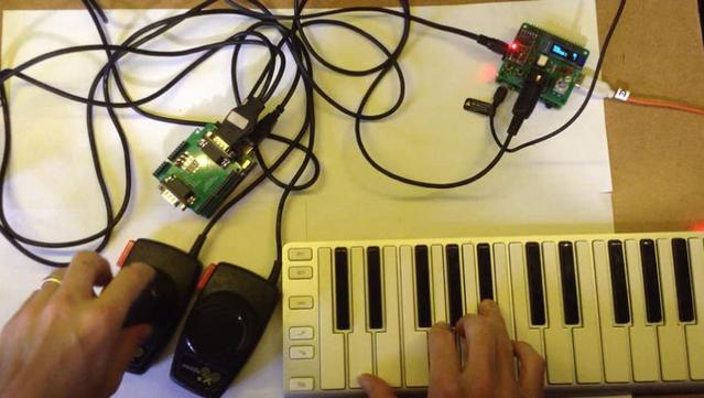
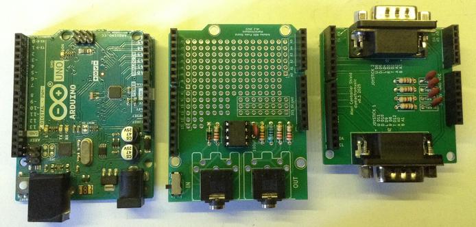
And now I can properly "properly" read all four paddles.

But that was a lot more complicated than I thought it would be. Even by the standards of my previous "that was a lot more complicated" statement!

Maybe I'm just a bit slow with this one! (or getting old) :)

Anyway, I finally have something I'm happy with. Now to actually do something with it!

(the things one does to avoid cracking open some vintage gear and changing it...)

https://diyelectromusic.com/2025/06/22/atari-2600-controller-shield-pcb-revisited-part-2/

#Atari #Atari2600 #Arduino

Atari 2600 Controller Shield PCB Revisited – Part 2

This has another look at my updated Atari 2600 Controller Shield PCB in order to attempt to read all four paddle controllers a bit more accurately and efficiently. Warning! I strongly recommend usi…

Simple DIY Electronic Music Projects

#CyanoStat: An #OpenSource #Arduino-controlled platform for #CO2 regulation in #microbial incubators optimized for #cyanobacteria #cultivation:

-add-on device for off-the-shelf microbial #incubator
-cost: 65 €

https://doi.org/10.1016/j.ohx.2025.e00649
#DIYbio #lab #research #science #instruments #microbiology

Ramin Djawadi, "Game of Thrones" (Arduino cover by avp):
https://www.youtube.com/watch?v=9DGQFEVbdcs

Programmed on a single Arduino Mega 2560 using timer interrupts.

The source code can be found in "examples" directory in the my book repository:
https://github.com/artyom-poptsov/SPARC

I'm working on a chapter in the book that is dedicated to low-level MCU programming. The current goal is to cover enough material to properly explain how to do such projects.

#arduino #music #sparc_book

Ramin Djawadi, "Game of Thrones" (Arduino cover by avp)

YouTube
I am ALL for #AI and #Claude and #GPT, etc. I do however, in my free time outside of work, school and creating STEM tutorials to help the next generation, believe that spending time in pure #Assembler in a bare-metal #Embedded #microcontroller will help you understand #Computer #Science in a way that can help you drive the future in #technology. I have and will continue to post pure Assembler drivers to help others achieve this utilizing #Arduino and #STM32 products.
×

OK, without any clock source this thing should barely draw any power.

Half a watt seems about right. Much more reassuring than the 286 was!

This is a 3V capable CPU though, so we'll run the board at 3V. It draws 0.1 W at 3.3V which is even better.

Still wondering what happened to my 80C286. Wish I had a system I could throw it in to see if it was actually dead or if I'm just a bonehead.

here's what i have to patch over to the Arduino

50% chance i have one or both of the address headers backwards lol

This should be it! It's the same gpio pinout as the 286 basically. The 386EX actually only has two more address lines. I guess 64MB of RAM is plenty for embedded applications...
Lucky that this header just happens to have CLK on it.
Conspicuously absent on the 386 is an ALE pin. I guess timings are now tight enough that you only concern yourself with the address when a read or write signal is asserted.
No bus status, no ALE pin... I guess I know the CPU has reset if it just reads something.

And I thought the 286 took a long time to reset.

450 cycles!

So far no response from the 386EX.

Time to do a sanity check to determine whether the RESET and CLK signals are really reaching the CPU.

The header provides a tie to /RST, that is an inverted RESET signal. This is one of the signals that passes through the inverter IC, a 74HC14D. I should check that the inverter is still receiving power after my board surgery, and that a positive RESET signal is coming out the other end of it.
Well, this is unfortunate. The holes in the board i assumed were for mounting posts actually seem to be connected to each plane and by putting screws in I have shorted the board.

The EX datasheet doesn't mention the particulars, but the SX datasheet has this to say:

I'm not sure how this board ties the busy pin. If it isn't low we're gonna be waiting a million cycles for it to reset.

BUSY is multiplexed with TMRGATE2 on Pin 92. It looks like this runs through a resistor network with a pulldown to ground (figures) but does go to a header pin curiously claled TMRCLK2. Typo perhaps? I hope so.

@gloriouscow Maybe they replaced it with a BEER pin?

(I show myself out)