The new #Si5351 implementation in HackRF is an even better improvement than I realized at first because the old, vendor-recommended algorithm introduces error by not rounding properly. The mean error of the old algorithm is approximately 256 times the mean error of the new one.

I think this is pretty great, but in practice this should rarely matter to HackRF users. The most commonly used sample rates are error-free integer divisions of the 800 MHz clock generator VCO.

I've recently used insights from this article to implement a sample rate step size 128 times smaller than previously supported in HackRF:

https://www.pa3fwm.nl/technotes/tn42a-si5351-programming.html

This means that sample rates around 20 Msps can be adjusted in steps of about 0.015 Hz. The precision is even better at lower sample rates.

I highly recommend reading it if you use #Si5351 in any projects. #Si5351A #Si5351B #Si5351C

Understanding and enhancing Si5351 programming

Arduino and SP0256A-AL2 – Part 6

Finally I’m doing something arguably slightly musical with my SP0256A-AL2! Playing it over MIDI.

  • Part 1 – Basic introduction and getting started
  • Part 2 – Arduino programmable clock
  • Part 3 – Using a Raspberry Pi Pico as a programmable clock
  • Part 4 – Using a HC4046 PLL as the clock
  • Part 5 – Using an I2C SI5351 programmable clock
  • Part 6 – Adding MIDI

https://makertube.net/w/wLRxeVHtMatYo7NGWCw54U

Warning! I strongly recommend using old or second hand equipment for your experiments.  I am not responsible for any damage to expensive instruments!

If you are new to microcontrollers, see the Getting Started pages.

The Circuit

This is using my Arduino SP0256A-AL2 Shield with an SI5351 programmable clock module, so this is essentially the circuit from Arduino and SP0256A-AL2 – Part 5 with the addition of a MIDI module.

I also used my Arduino MIDI Proto Shield but any MIDI RX circuit on the Arduino RX pin would work.

The same circuit can be made on solderless breadboard, but I’ve opted to use my PCBs for convenience as that is why I designed them in the first place.

The Code

I’m using all the main code from Arduino and SP0256A-AL2 – Part 5 but I’ve split the speaking into “start” and “stop” parts so I can drive them from MIDI NoteOn and NoteOff messages.

The main “speak” code now looks like the following:

void speak (uint8_t note) {
if (note == 0) {
spAllo(PA3); // Speaking off
return;
}

if ((note < MIDI_NOTE_START) || (note > MIDI_NOTE_END)) {
return;
}

midi2clock (note);
switch(note){
case 36: // Do
case 37:
case 48:
case 49:
spAllo(DD1);
spAllo(OW1);
break;

case 38: // Re
case 39:
case 50:
case 51:
spAllo(RR1);
spAllo(EY1);
break;

...

So when called with note==0 it will stop the speaking by sending PA3, but for any note between 36 and 56 it will set the frequency and then say the appropriate “Do, Re, Mi” word. I’ve used the same word for the natural and sharp equivalent. I’ve also allowed for two octaves. This is why there are four note values that result in the word “Do” being said: MIDI notes 36, 37 (C2 and C#2), 48, and 49 (C3 and C#3).

This can now be called from the code that handles MIDI Note On and Note Off messages.

Find it on GitHub here.

Closing Thoughts

It works, but it isn’t very responsive due to the time it takes to say each allophone.

I guess when I started thinking about doing this, I thought I’d get more of a frequency range from the device and wasn’t anticipating it being so “low” in the musical range either.

But it is quite fun to see it finally being driven by a music keyboard, even if it isn’t particularly practical!

I know there is emulation of an SP0256A-AL2 in the RC2040 (an emulation of the RC2014 on a Raspberry Pi Pico) so I might at some point look at seeing if I can just drop the hardware and doing it all in software at some point by adjusting sample and playback rates.

I suspect that will work a lot better, but it isn’t quite the same as driving the real thing 🙂

Kevin

#arduinoUno #midi #si5351 #sp0256aAl2

Arduino SP0256A-AL2 Shield PCB Build Guide

Here are the build notes for my Arduino SP0256A-AL2 Shield Design.

Warning! I strongly recommend using old or second hand equipment for your experiments.  I am not responsible for any damage to expensive instruments!

If you are new to electronics and microcontrollers, see the Getting Started pages.

Bill of Materials

  • Arduino SP0256A-AL2 Shield PCB (GitHub link below)
  • 1x SP0256A-AL2 (see notes here on sourcing: SP0256A-AL2 Speech Synthesis)
  • Either 1x 3.579545 MHz oscillator (4-pin in 8-pin DIP footprint – see photos)
  • Or 1x SI5351 breakout board (see photos)
  • 2x 1KΩ resistors
  • 3x 100nF ceramic capacitors
  • 1x 1uF electrolytic capacitor
  • 1x 3.5mm stereo TRS socket (see photos and PCB for footprint)
  • 1x set of Arduino headers: 1x 10 pin; 2x 8 pin; 1x 6 pin
  • Optional: 1x 28 pin wide DIP socket

Build Steps

Taking a typical “low to high” soldering approach, this is the suggested order of assembly:

  • Resistors
  • DIP socket (if used) and TRS socket.
  • Disc capacitors.
  • Electrolytic capacitor.
  • 3-way jumper headers.
  • Oscillator (if used)
  • SI5351 pin headers (if used)
  • Arduino headers

It should be decided up front if the board will use a fixed oscillator or a SI5351 programmable clock. Both could be installed, but there is a solder bridge that has to be used to determined which will be used. It isn’t possible to use both at the same time.

This shows the solder bridge configured to use the SI5351. This might be easiest to do prior to soldering other components on the board.

Here are some build photos.

Here is a photo with the oscillator installed, and one with the SI5351 instead.

Note: I didn’t solder the pin headers of the SI5351 to the PCB, but instead used the “fishing line trick” to push the board into the PCB without soldering. This means I have the option of reusing the board again for something else in the future.

By default the SP0256A-AL2 /RESET line is connected to the Arduino RESET pin. It is possible to break this link by cutting the solder bridge shown below and wiring the RESET pad to another Arduino GPIO pin.

Testing

I recommend performing the general tests described here: PCBs.

PCB Errata

There are no known issues with this PCB at this time.

Enhancements:

  •  With hindsight it might have been useful to have a jumper option to select the clock mode rather than a solder bridge. But it seemed quite a fundamental choice at the time of designing the PCB that I thought it perhaps shouldn’t be quite so easy to change. Now I’m not so sure!

Find it on GitHub here.

Sample Applications

Here are some applications to get started with:

Closing Thoughts

Now it is a bit easier to experiment I can explore a few other musical possibilities.

But this has shown up a slight issue with the chips I have. The highest frequency that the chip can support without locking up seems to be somewhat device dependent.

I’ve seen nothing in the datasheet, application manual, or design guide that suggests it will function at all with anything other than a 3.12MHz oscillator, so I am running it quite a bit out of specification now.

Kevin

#arduinoUno #pcb #si5351 #sp0256aal2

Arduino SP0256A-AL2 Shield Design

Having spent quite a bit of time with an Arduino hooked up to an SP0256A-AL2 on a solderless breadboard, and now that I’ve got some ideas for how I want to sort out the clock, I thought it time to create a PCB to save the unreliable wiring getting in the way!

Warning! I strongly recommend using old or second hand equipment for your experiments.  I am not responsible for any damage to expensive instruments!

If you are new to electronics and microcontrollers, see the Getting Started pages.

The Circuit

This is the basic circuit I’ve been using since Part 1 but I’ve added in an option to support the SI5351 from Part 5 instead of the oscillator, too. A solder jumper selects the clock source – there is no default setting.

There is also a (default closed) solder jumper on the RESET line in case there is a need to separate out the reset of the SP0256A-AL2 from the Arduino.

PCB Design

The PCB design is relatively straight forward. Using an Arduino Uno Shield template, all the components have fitted in quite well.

I had to create a custom symbol and footprint for both the SP0256A-AL2 itself and the SI5351 module I’m using.

The following GPIO pins are in use.

ArduinoSP0256A-AL2D2-D7A1-A6D8/ALDD9SBYGNDVSS, A7, A8, TEST, OSC2+5VVDD, VDI, SE, /SBY_RESET/RESET/RESETSI5351 (Optional)A4SDAA5SCLGNDGND+5VVIN

As already mentioned, the link between the two /RESET pins is via a solder jumper and pin header connection which can be broken if required.

I’ve added in additional breakout headers for all GPIO that isn’t connected to the SP0256A-AL2: D0-D1, D10-D13, A0-A3.

I’ve not included A4-A5 as these are connected to the SI5351 (if used).

Closing Thoughts

Hopefully this is a fairly straight forward design with no major surprises.

Kevin

#arduinoUno #pcb #si5351 #sp0256aal2

Si5351 CLK1 Output: Adding two low pass and one high pass filters cleans this right up. Spurious are now > 50 dBc!
#HamRadio #TestEquipment #Si5351

Driving the SP0256A-AL2 from an Arduino with a SI5351 I2C programmable clock.

This is starting to get useful now (finally) :)

https://diyelectromusic.com/2025/09/08/arduino-and-sp0256a-al2-part-5/

#Arduino #SP0256AAL2 #SI5351

Arduino and SP0256A-AL2 – Part 5

This looks at another of the options from Part 4 – the I2C programmable Si5351 clock source. Warning! I strongly recommend using old or second hand equipment for your experiments.  …

Simple DIY Electronic Music Projects

Arduino and SP0256A-AL2 – Part 5

This looks at another of the options from Part 4 – the I2C programmable Si5351 clock source.

  • Part 1 – Basic introduction and getting started
  • Part 2 – Arduino programmable clock
  • Part 3 – Using a Raspberry Pi Pico as a programmable clock
  • Part 4 – Using a HC4046 PLL as the clock
  • Part 5 – Using an I2C SI5351 programmable clock
  • Part 6 – Adding MIDI

https://makertube.net/w/bX5QNRRkAomFJQo7qY17he

Warning! I strongly recommend using old or second hand equipment for your experiments.  I am not responsible for any damage to expensive instruments!

If you are new to microcontrollers, see the Getting Started pages.

I2C Si5351 Programmable Clock

From the datasheet of the Si5351:

“The Si5351 is an I2C configurable clock generator that is ideally suited for replacing crystals, crystal oscillators, VCXOs, phase-locked loops (PLLs), and fanout buffers in cost-sensitive applications. Based on a PLL/VCXO + high resolution MultiSynth fractional divider architecture, the Si5351 can generate any frequency up to 160 MHz on each of its outputs with 0 ppm error.”

The device itself requires a 3V to 3.6V supply, but typical breakouts seem to include a LDO regulator meaning it can be powered from 3V to 5V. Logic outputs are always 3V but the I2C lines will be the same as the power supply.
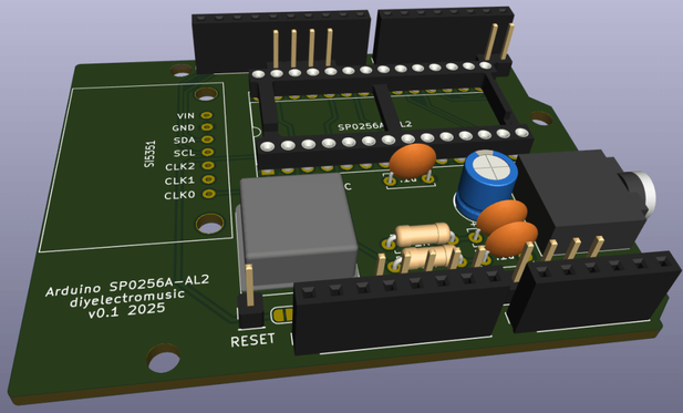
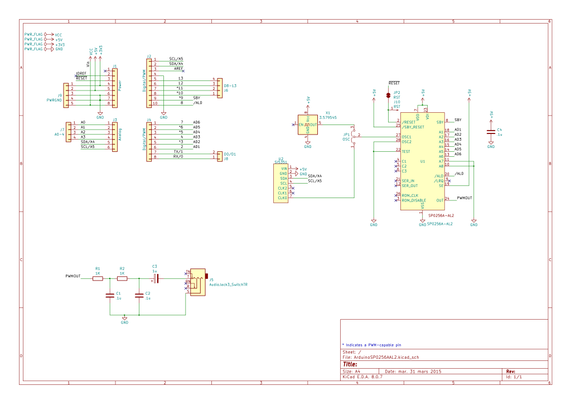
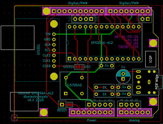
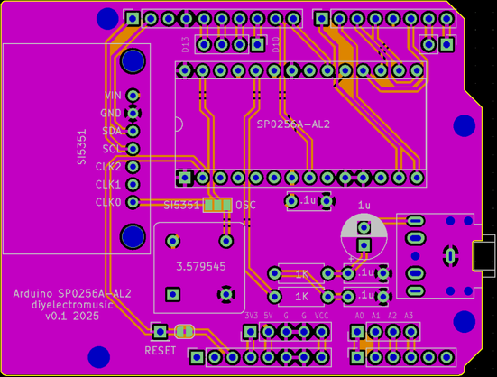
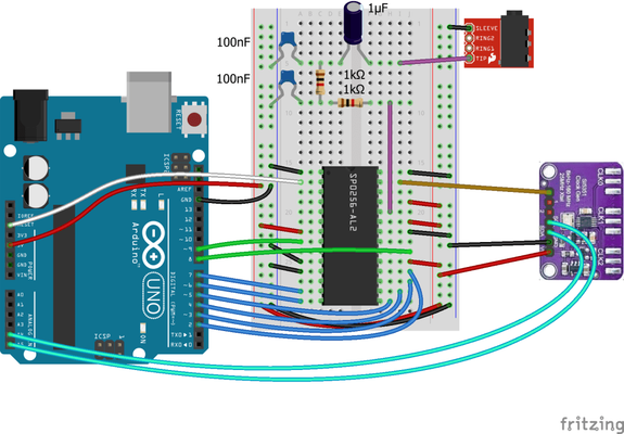
The Circuit

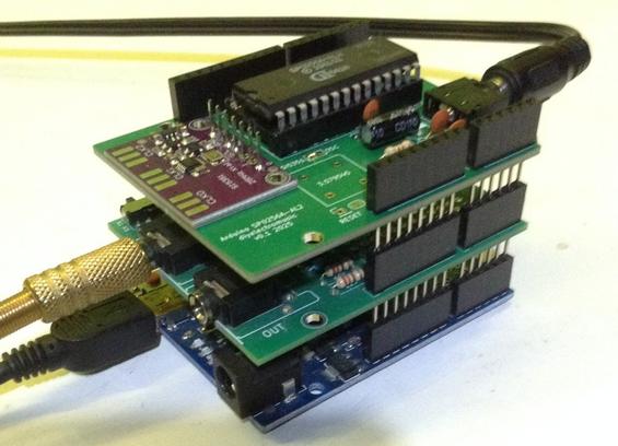
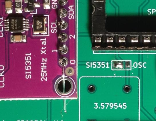
I’m using a breakout board like the one shown above. This has header pins for the three clock outputs, power and ground, and I2C. Although the si5351 device itself is a 3V3 device, most breakouts like this seem to include components to allow them to be powered by either 3V3 or 5V. I’m using 5V in my circuit.

I’m only using one of the clocks, so output 0 is fed into the OSC1 input of the SP0256A-AL2. Otherwise the rest of the SP0256A-AL2/Arduino circuit is the same as for part 1.

The Code

There are two libraries I’ve found for this:

The Adafruit library is a fairly low-level interface to the device. The device basically has a multiplier which is used to set a PLL clock to somewhere between 600 and 900MHZ; and then a divisor to drop that back down to something useful.

But the reality of setting the parameters is actually quite complicated. There is a full discussion of how to do it, with some example Arduino code, here: https://rfzero.net/tutorials/si5351a/

It is not for the faint hearted!

Thankfully the second library mentioned above, by “EtherKit”, has a ‘set_freq()’ function that does it all for us. The code to use it is therefore fairly straight forward:

#include <si5351.h>
#include <Wire.h>

Si5351 si5351;

void clockSetup () {
si5351.init(SI5351_CRYSTAL_LOAD_8PF, 0, 0);
si5351.set_freq(300000000ULL, SI5351_CLK0);
si5351.update_status();
}

void setClock (uint64_t freq) {
si5351.set_freq(freq, SI5351_CLK0);
si5351.update_status();
delay(300);
}

The initialisation function requires three things:

  • Which of 6, 8 or 10pF capacitors are used with the external oscillator.
  • Frequency of the external oscillator. Passing in 0 uses the default, 25MHz.
  • A parameter for frequency correction. I’m just using 0.

The set_freq() function takes a 64-bit value which gives a frequency in 0.01Hz units, so 3MHz is 3 followed by 8 zeros. This is an “unsigned long long” type, hence the “ULL” initialiser after the value in the code above. The other parameter states which clock to use – I’m just using clock 0.

It is possible to wire up a pot to an analog input and set the frequency using something like the following:

int alglast = 0;
void checkClock (void) {
int algval = analogRead(ALG_IN);
if (algval != alglast) {
uin64_t freq = 1000 + 5 * analogRead(ALG_IN); // in kHz
setClock(freq*100000); // Convert to 0.01Hz units
}
alglast = algval;
}

This maps a pot reading onto frequency values between 1MHz and just over 6MHz in units of 5kHz.

Alternatively, it is possible to set pitches for individual allophones. I’ve found that loosely speaking, 3MHz seems to correspond to talking at the pitch of G#2 (MIDI note 44) which is an audio pitch frequency of round 98Hz. 6MHz is, as you might expect, G#3 (MIDI note 56 at 196Hz).

This means that the I can calculate the required clock frequency for a MIDI note M using the formula:

  • Freq = 3MHz * 2 ^ (M – 44)/12

This function will set the clock based on the MIDI note number:

void midi2clock (int m) {
if (m < 36 || m > 56) {
return;
}

freq = 300000000 * pow (2.0, (((double)m-44.0)/12.0));
setClock (freq);
}

Note how I’ve limited the range to between C2 (36) and G#3 (56), which means frequencies of 1.889MHz to 6MHz.

It would probably go a bit lower – down to 1MHz is probably practical from the point of view of the chip functioning, but not so useful from the point of view of how long it would take to say a single allophone. Anything higher will cause the SP0256A-AL2 to lock up in a funny state.

But that gives me a good octave and a fifth, which is quite a useful and practical range.

Warning: The top frequency seems to be device dependent for me. I have one that can support the full 1.5 octaves and one that locks up after just an octave, so some experimentation is required!

Find it on GitHub here.

Closing Thoughts

This is the most accurate and simplest to set up manner of providing a programmable clock I’ve found so far. The device itself is actually quite complex to use, but all that complexity has been hidden away in the Si5351 library published by EtherKit.

The device sometimes seemed to get stuck in a weird state where is wasn’t recognised on the I2C bus. A power cycle or reset, or some combination of both, was usually required to get it going again. I don’t know if that was dodgy cables somewhere, but when it got stuck, curiously my nearby FM radio receiver lost its signal… Hmm.

The downside of using the Arduino for both clock and speech control is that it isn’t possible to adjust the clock whilst the speech is happening. That would need some kind of parallel execution to manage that – either adding in another microcontroller, or maybe moving to a dual-core microcontroller.

But as you can hear from the end of the video, this could still be pretty useful and I wish I’d had it for my Electric Lo-Fi Orchestra Concerto for a Rainy Day.

Kevin

#arduinoUno #electricLofiOrchestra #include #si5351 #sp0256aAl2

Arduino, SP0256A-AL2 and Si5351 Programmable Clock

https://makertube.net/w/bX5QNRRkAomFJQo7qY17he

Arduino, SP0256A-AL2 and Si5351 Programmable Clock

PeerTube