I just put in an order for some replacement parts I messed up on my RV-10 elevator as well as the sealant kit they recommend. So I think I'm getting ye olde motivation to go finish those elevators.
Here is a very short video clip of me installing a pull rivet from the inside view. The Zenith CH750 gets a tiny bit closer to done.
#rivet #riveting #experimentalAviation #homebuilt #kitplane #avgeek
The glider now has 12 pounds of lead shot and epoxy added to dead space in the very end of the tail boom.
My initial estimate of volume indicated that I could add 8 - 10 pounds this way. I'm pleasantly surprised, and I didn't make a chocolate covered mess of things as I was pouring this goop into the tail.
I need to add a few more pounds to the tail. Phase two of this project will use lead plate, bolted to the vertical fin spar. (I need to unroll the 1/4-inch plate first, then develop a template to cut the lead.)
I could not add the epoxy/lead shot mix all at once because of the exothermic reaction of epoxy. When mixed epoxy is in a thick blob (instead of a thin layer), it generates enough heat to warm itself...which accelerates the chemical reaction...releasing more heat...further accelerating the reaction.... I have seen epoxy smoking hot because of this, so I added a bit, waited a half hour, checked temperature with an IR non-contact thermometer, added a bit more when it was clear that the exotherm was only very mild, etc. That took a while, but turned out well.
I note that Roto Metals has a discount on some 1-inch lead plate. Get your fork lift ready. No free shipping!
https://www.rotometals.com/lead-sheet-plates/sheet-lead-1-64-lbs-sq-ft/
#AvGeek #Aviation #ElectricAircraft #Homebuilt #Glider #DIY #EAA #Ballast #Math #Density #Exothermic #Chemistry #Thermodynamics #Lead #Epoxy
The workshop was pretty neat. Aside from learning a bunch of the theory and getting recommendations for books and whatnot, you do some hands on stuff which is always a great way to learn. On day one we did various crimping practice and made a wire harness connected to aviation headset jacks and once we were done, we plugged it into an actual intercom to test it (and it worked, which feels great).
Second day we went over antenna theory and some things there, then made a coax cable end (tedious to be sure). The final project was soldering and crimping to simulate building a part of a panel. Basically a lighting circuit for nav lights and the panel lighting is tied to it with a dimmer. My soldering skills are fairly out of date but I managed all the same.
It was a neat class and I look forward to using some of that knowledge on the builds I'm helping with (as well as my own).
The glider's 3rd battery now has a sewn carrying handle that makes it easier and safer to install in the crowded battery box.
Next, I need to devise a retaining system for it and finish the wiring harness that connects it to the rest of the system.
Progress will slow for the next day or two because the things I have ordered (epoxy, lead shot, etc.) will be delayed while we ride out a snowstorm that should end tomorrow.
#AvGeek #Aviation #ElectricAircraft #Homebuilt #Glider #DIY #EAA #Safety #Battery #Sewing
Where does the 'typical' glider battery go in this electric glider?
In the battery box, next to the high voltage motor batteries.
My final decision on this battery location depended on the weight and balance measurements I made last week. It shows that I need to add weight to the tail...so, the heaviest batteries are full-aft in the battery box, and this 3rd battery goes in front. All of this is aft of the tail in the fuselage/tail boom.
I now need to sew some sort of sack and carrying handle for this battery. It's not a heavy battery, but I want a secure way to handle it as I install/remove it.
Above my hand is a black/gray marbled-pattern object. It's a yoga block. That semi-dense foam will be cut to size to take up any dead space along the sides of the battery box to prevent the batteries from banging side-to-side if the other retaining systems fail.
#AvGeek #Aviation #ElectricAircraft #Homebuilt #Glider #DIY #EAA #Safety #Battery
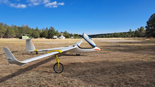
My glider will use a tow rope that is too strong. That rope, when under maximum pull, may damage the glider.
I need to install a weak link as a mechanical 'safety fuse'.
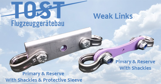
Here is one weak link system I can use:
https://wingsandwheels.com/tost-weak-link.html
But which weak link is appropriate for my glider?
Federal Aviation regulations require a tow rope (or weak link) to have a certain breaking strength with regard to the maximum operating weight of the glider:
"The towline used has breaking strength not less than 80 percent of the maximum certificated operating weight of the glider or unpowered ultralight vehicle and not more than twice this operating weight."
https://www.ecfr.gov/current/title-14/chapter-I/subchapter-F/part-91/subpart-D/section-91.309
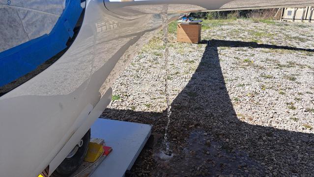
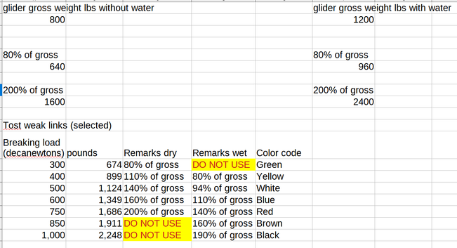
To complicate matters, my glider can carry 400 pounds of water ballast. When I'm flying 'dry', I would prefer to have a weak link that is just strong enough for the dry glider, and when flying 'wet' I would prefer a (somewhat stronger) weak link appropriate to the heavier operating weight.
See the second graphic, which shows which Tost weak links I can use in the dry or wet ballast condition.
I will start out getting the weakest weak links allowed (green, yellow, and white) and see if that launches me well without premature weak link breaks.
Pro-tip. Try not to lift the rear end of the ground launch car.
https://youtu.be/kd9QxRPb3hk?t=33
#AvGeek #Aviation #ElectricAircraft #Homebuilt #Glider #DIY #EAA #Math #Weight #Safety
My glider needs the center of gravity shifted aft, so I need to add weight in the tail.
The first photo is looking into the rudder cove (rudder removed). I can bolt some lead plates to the flat face of the vertical fin spar, but I will need even more weight added back here.
Note that the rudder hinge support is glowing green...a flashlight on the other side is illuminating it.
That part is hollow and it's nothing but dead space. I can add lead shot and epoxy in there.
The second photo shows the view of this pale green fiberglass part from the other side. Before I can add lead shot in there, I need to add a dam to retain it while the epoxy cures.
Third photo shows a piece of scrap Plexiglas that fits up against the end of the rudder hinge support.
Final photo shows the Plexiglas dam glued into place with RTV silicone caulk. It has a semicircular cutout that allows a larger diameter piece of tubing to be placed there while I pour lead shot and epoxy into a funnel and fill that empty space.
Half of the caulking work was done blind and by feel. I am accessing this tight space from the inspection port in the side of the vertical fin. There is just enough room for one hand and this part to pass through the port and then get positioned. I practiced before applying the caulk so I knew exactly how to position and twist the part so that I didn't make a mess and most of the caulk ended up in the desired location.
#AvGeek #Aviation #ElectricAircraft #Homebuilt #Glider #DIY #EAA #Epoxy #Ballast #Lead #Plexiglas
Like most GA aircraft, my plane has a very loud interior. Whenever I fly, my watch fairly constantly warns me about excessive noise levels. Usually 95 db, occasionally I see 100 db. Noise cancelling headsets are basically required to be in the aircraft while the engine's running. But even then, the noise is still noticeable.
Searching on the vansairforce forums (<3 old school forums), it seems that a lot of the cause of excessive cabin noise is basically panels vibrating against each other, and adding soundproofing material (tape, foam, etc.) helps to massively reduce the noise. The problem then becomes an optimization problem of where to apply the soundproofing to maximize effect while minimizing weight.
I'm thinking of taping a bunch of cheap mics to various spots in the airplane, recording the sound amplitude to try to figure this out. I'm hoping to be able to achieve a noticeable decrease in sound levels doing this.
Of course, I'll also decrease sound levels by just adding carpet to various panels, which I want to do anyway (my cabin is spartan). But I also want to see what the combined improvement will be.
The electric glider's two main batteries each weigh about 16 Kg (36 lbs). I need a positive restraint system that can handle vibration and especially negative G.
Yesterday evening I epoxied in place some retaining blocks for the two battery clamping bars, but the garage gets cold overnight. I placed an incandescent lamp over the top of the battery box and wrapped some towels as a 'tent' to keep the warm air from easily escaping. This allowed the battery box to stay slightly warmer and accelerate the curing of the epoxy.
The second photo shows one end of a battery clamping bar (yellow) that fits under a carbon fiber inverted shelf (black). On each side of the clamping bar there are now two blocks of garolite (pale green) that prevent the battery block from sliding off to the side.
Garolite (G-10) is commonly used as the substrate for printed circuit boards, and you can get it in significant thickness, which is what I need.
https://en.wikipedia.org/wiki/G-10_(material)
#AvGeek #Aviation #ElectricAircraft #Homebuilt #Glider #DIY #EAA #Epoxy #Chemistry #Temperature #Garolite