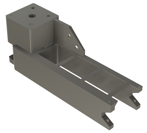
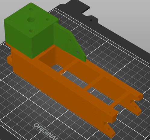
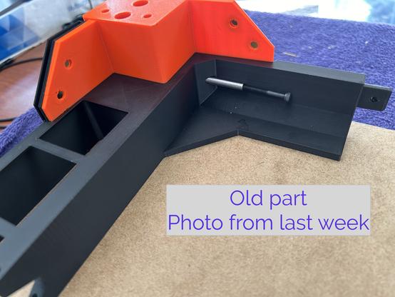
I do not understand components and coordinate systems in Fusion 360. Because of that, I may have lost the design I've been drawing all week.

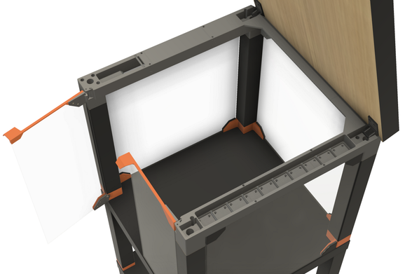
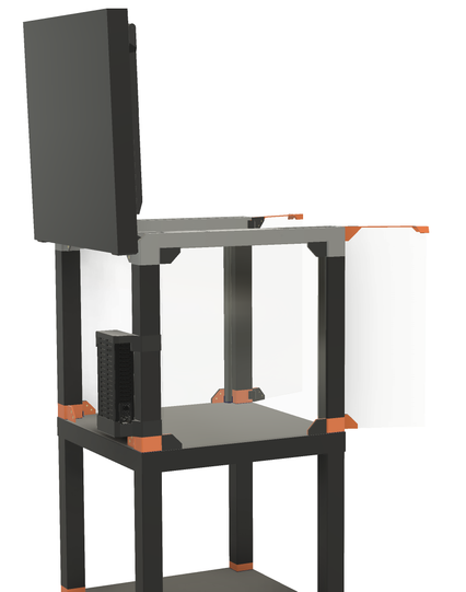
I changed a parameter, and half the things that should have moved did move, and half did not. Curves that had been closed were no longer closed, and things got worse from there.

It looks like parameters used in the Move/Copy command don't update? Do I have to use a rigid joint to fix every component?

Advice welcome.

I also have grouped things into components incorrectly. For example, I made the two halves of a hinge into one component, because the parts have to mate, and they share sketches and dimensions. But to open the door, the moving part has to be a separate component. I feel like I'm missing something basic.

Yeah, so I started over. Now I'm tying components together with rigid joints and tying them to points on sketches whose measurements use parameters. This is the measurement I tweaked that blew my model up last time...

Maybe I should hashtag this thread. #Fusion360 #MCAD

Wheee! Look at me! I figured out how to get two hinges and a door to move in sync. (Revolute joints for each hinge pin, rigid joints between the pieces, then let F360 figure out the rest.) Anyway, the LACK printer enclosure continues slowly.

#Fusion360 #MCAD

That's darn good graphics too.

As promised, there's just a little #gridfinity storage under the lid.

It's about time to stop pushing pixels and start melting filament. I think this is at least a week of print time and about three Kg of PETG, if I get everything right on the first try. Which I won't.

@3dprinting #3DPrinting #BlackLackStackHack #IkeaHacks

@3dprinting I'll also have an IKEA MOSSLANDA shelf on the front with another 2x12 #gridfinity slots. My old printer enclosure has that, and I like it a lot.

@3dprinting This is part of the top rail where the Gridfinity bins go.

The two rail pieces are held together by dowel pins, and they are tight and rigid. I made the grid floor a separate insert because I couldn't get a good surface finish when it was printed upside down. (And now it's a contrasting color.) The grid floor is also two pieces joined by dowel pins.

The rest of this rail is on the printer now.

@3dprinting #BlackLackStackHack #3DPrinting #GridFinity

@3dprinting The bottom of the slot between the rails is 0.2mm wider than the top, so the gridfinity tray snaps into place and isn't coming out. (I can push it out from the bottom.) I tried 0.8mm on the first iteration, but I couldn't force the tray in.

#BlackLackStackHack #3DPrinting #GridFInity

@3dprinting The purple piece is the end cap for the LED channel. It press fits into place. The wires will feed into the channel from the other end. This will probably be one of the trickier bits to assemble when sliding this down onto all four legs at once.

The filament is Prusament Ultramarine Transparent PETG. The other colors are Prusament Prusa Orange and Prusament Matte Black. The ultramarine is outside the gamut of most LCD screens.

#BlackLackStackHack #Prusa3D #3DPrinting

@3dprinting The orange post on top is not a separate piece. I did a layer height color change.

#BlackLackStackHack #Prusa3D #3DPrinting

@3dprinting Here's the other end of the LED channel. It's open on the bottom for wires. I can drill a hole through the table anywhere that is hidden by the square plate and doesn't interfere with the screw holes. I think I'm using JST SM connectors, so the hole needs to be that big.

This is by far the most complex mechanical assembly I've ever designed.

#BlackLackStackHack #Prusa3D #3DPrinting

@3dprinting The hinges have bar magnets to hold them closed. That's from Prusa's design, but I moved them to give them about 60% more mechanical advantage and increase the closing force. They feel very satisfying to operate, but I won't know for sure until the doors are attached.

#BlackLackStackHack #Prusa3D #3DPrinting

@3dprinting Color change! And now I can go to bed.

#BlackLackStackHack

@3dprinting I suspect most of you, like me, get to see the insides of IKEA furniture far too rarely. So here's a LACK table undergoing surgery.

Now I'm trying to excavate out to the corner to find out how much wood is there for the legs. I want to run a cable in next to the leg and hide it inside...

#IkeaHacks

@3dprinting Calling it wood was far too generous. As I expected, there's a block of sawdust-glue porridge in the corner just slightly bigger than the leg. It's hard to measure in there, but it looks like it extends about 60mm from each table edge. When I drill the hole for the cable, I can get a better measurement.

#IkeaHacks

@3dprinting Now that we know where the solid parts are inside the table, we see that most of the screws in Prusa's enclosure design are screwed into air. Hmmm...

(Source: https://blog.prusa3d.com/mmu2s-printer-enclosure_30215/ )

#BlackLackStackHack #Prusa3D #IkeaHacks

Prusa Printer Enclosure V2 - with MMU2S support - Original Prusa 3D Printers

Our first 3D printer enclosure became incredibly popular - and naturally, once we released our new Multi Material Upgrade 2.0 and 2S, people started asking us for an updated enclosure that would accomodate the Original Prusa i3 MK3S (and 2.5S) 3D printer...

Original Prusa 3D Printers

@3dprinting I redrew the prop arm to move the bracket to the corner of the table. Numerous picky little changes later...

#BlackLackStackHack

@3dprinting This joint locks two PETG pieces together far better than it has any right to. I had to force the pieces together with Knipexes.

I'm printing the prop arm (previous toot) in two interlocking pieces. Prusa's design used a very loose mortise and tenon with Superglue.

#Prusa3D #BlackLackStackHack

@3dprinting Here's the new prop arm and the tool that squeezed it together. The pieces aligned pretty straight but not perfect.

Note that the two halves of the arm were printed in different orientations. I had to print the left half with support.

#Prusa3D #3DPrinting #BlackLackStackHack

@3dprinting I've solved the problem of mounting LEDs to the underside of the LACK table in my printer enclosure. I'm very happy with the result.

#3DPrinting #IkeaHacks #Prusa3D #BlackLackStackHack

@3dprinting ??? This was supposed to be a video. It looks like I just uploaded a still.

#3DPrinting #IkeaHacks #Prusa3D #BlackLackStackHack

@3dprinting I am still working on the printer enclosure when I'm not traveling. Today I made a test piece that slides along an IKEA LACK leg. I put steel dowel pins on two sides for a tight but low-friction fit. It works better than expected.

#IkeaHacks #BlackLackStackHack #Prusa3D

@3dprinting I plan to put the printer's power supply outside the enclosure attached to one table leg. The bottom of the power supply will fit into a cradle, and a cap will slide down over the top of the PS to keep it stable. To remove, I'll just slide the top up and lift the PS out.

#IkeaHacks #BlackLackStackHack #Prusa3D

@3dprinting It took the entire day, like 12 hours, just to model this power supply cover. It doesn't look that hard, but it took a long time to collapse the infinite possibilities down to this one. It's on the printer now; I'll see if it fits in an hour.

#IkeaHacks #BlackLackStackHack #Prusa3D

@3dprinting I adjusted a few dimensions, and the second try fits nicely. There's just barely room enough (I hope) to bend the wires around and connect them into the jack.

This is the same receptacle Prusa uses for their enclosure's optional quick release. So if I ever move my printer into one of those, it will be ready to plug in. https://www.prusa3d.com/en/product/psu-cable-quick-release-for-original-prusa-enclosure-mk4/

#Prusa3D #BlackLackStackHack

PSU Cable Quick-release for Original Prusa Enclosure (MK4) | Original Prusa 3D printers directly from Josef Prusa

A quick-release connector for the 3D printer’s PSU cables. This is an ideal solution for everyone who often takes the printer out of the enclosure. This spare part is compatible only with the Original Prusa Enclosure.

Prusa3D by Josef Prusa

@3dprinting Here's the power supply mount I came up with. The upper bracket slides up, and the power supply can be removed without tools. That way I can take the printer to the bench without a lot of hassle.

The AMP MATE-N-LOK connector is rated for 70 amps! The power supply is rated for 10.

#BlackLackStackHack #Prusa3D

@3dprinting It will go outside the enclosure on the back side, as shown here.

#BlackLackStackHack #Prusa3D

@3dprinting The cable passes through the foot under the leg to another MATE-N-LOK connector inside the enclosure.

You can see ribs on the upper bracket. Those house the dowel pins I'm using as bushings for the slider. I posted photos of the prototype of that upthread on May 9th.

#BlackLackStackHack #Prusa3D

@3dprinting Unrelated, but also visible in the first photo above, the purple ("aquamarine") hexagonal tube in the lower left is for the LED wiring. The LED power supply will be underneath, and one strip of LEDs will be in the enclosure lid. Power and signal will run through that tube and up through the leg to the lid.

#BlackLackStackHack

@3dprinting Stupid Fastener Tricks, Episode 87.

These dowel pins I got on Amazon have internal threads. I had no idea why, but I got 'em anyway. Turns out they're pretty useful for inserting/removing them into deep holes and making 100% hidden hinge pins.

#BlackLackStackHack #Prusa3D

@3dprinting I feel like I'm rediscovering really basic things here. It's like the MCAD equivalent of putting an if statement inside a for loop to only process some of the elements of an array: trivially obvious to anyone who's ever done it before. But I've never done it before. So it's new and exciting.

@3dprinting I have finally started assembling the Black LACK Stack Hack (printer enclosure). I am nothing if not slow^Wdeliberate.

I found out that the "plugs" that go between the hex nuts and the table corners (the red parts) are too tight to slide over the threaded rods. I tried forcing one on with the flywheel wrench, but that got old. So I'm printing new plugs now.

(The flywheel wrench works very well.)

#BlackLackStackHack #Prusa3D #3DPrinting

@3dprinting Here's the next layer. At this point, I should stop and do some more design. I want to attach several things to the underside of the next table, and I'm not sure they'll all fit. Nor how to attach them.

- a rackmount power distribution unit in back
- steel sheet storage in front
- a Gridfinity shelf in front
- LED power supply and cabling
- Raspberry Pi or mini PC for Octoprint

#BlackLackStackHack #Prusa3D #3DPrinting

@3dprinting I spent some time mulling design possibilities for that checklist and decided to defer those features. But the PDU did come in yesterday, so I installed that.

#BlackLackStackHack

@3dprinting Stupid Fastener Tricks, Episode 88.

To hide the screws on the power distribution unit, I printed some plastic covers that are held in place with magnets.

This brings the total magnet count in this enclosure to 120, I think. If I put a shelf of Gridfinity slots in front, that'll be another 48 magnets.

#BlackLackStackHack #Prusa3D

@3dprinting One more layer. This is the surface the printer will sit upon.

This is by far the most rigid IKEA furniture I've ever handled. So that validates the steel rod idea.

But the back right rod is not parallel to the others now. I must have torqued it somehow. The rest of the assembly seems square. Not worrying yet.

#BlackLackStackHack #Prusa3D

@3dprinting After all the progress I've made on the Black Lack Stack Hack recently, I was due for a setback. I carelessly picked this assembly up by one end to show it to someone, and it cracked under its own weight. When it hit the floor, the opposite joint cracked too.

They were wobbly anyway, so I should design something better.

Edit: two more photos.

#BlackLackStackHack #Prusa3D

@3dprinting I spent yesterday designing a new joint. I ended up using a bigger mortise/tenon plus three dowel pins. (I really love dowel pins.) The pins are 5x50mm and 3x30mm. The screw is M3x10.

I printed these two test pieces to verify fit. They are plenty rigid, and I have to pry them apart with a screwdriver. This is definitely overengineered. (I really love overengineering things.)

#BlackLackStackHack #Prusa3D

@3dprinting The bad news is that the two parts that broke are the two longest-printing parts in the whole enclosure. Reprinting all three parts is about 15 hours. Fortunately, I started last night...

#BlackLackStackHack #Prusa3D

@3dprinting One more layer. The cord at the back left is for the addressible LED strip in the lid. It was a pain to fish through. It is a power cord with the ends snipped off; I'll crimp on some JST SL connectors later.

I've been looking at the CAD drawing for so long that it doesn't even look like a new thing.

#BlackLackStackHack #Prusa3D

@3dprinting One more layer. I test fit one door and one window. Each door is held on by 4 magnets and has another four keeping it closed. Each window is held on by 8. The windows have just the right amount of magnetic glomp (technical term). The door is kind of wobbly but it stays closed.

I have errands for the rest of the day, so the lid will have to wait.

#BlackLackStackHack #Prusa3D

@kbob 😬 Did it break on layer lines?
@chrishuck No. The layer lines were running the horizontal direction. It was just too small, with too few perimeters.
@chrishuck Orientation.
@kbob Gotcha. Classic failure in bending with not enough “fibers” to handle the tension/compression. PLA’s brittleness would help either. That is, if it is PLA?
@kbob @3dprinting I really gotta get back into deposition printing again. Resin printing has made me lazy lol
@kbob @3dprinting what keeps them in the hole? Friction? Glue? Heat setting?
@linux_mclinuxface @3dprinting Friction. The last 3mm of the hole is undersized.
@3dprinting The photos are outdoors because my office is on the east side of the house and kind of dark this late in the day. Since I had to move to the west side anyway, and it's nice out, ...
@kbob This is a great idea!
@chrishuck That's high praise coming from you.
@kbob I think it’s a clever solution that is easy to print. Further proof that everyone has good ideas!
@kbob @3dprinting these are neat feet? What do the rods do?

@reconbot @3dprinting The metal dowel pins slide along the table leg. Steel is harder than plastic, so it deforms less and keeps the piece aligned better, and it's smoother, so it slides easier.

(Did I understand your question?)