Stemma, Grove, QT, Gravity, Duppa, I2C
I’ve always liked the look of these “plug the sensors in using I2C” different options out there, but must admit I’ve never really got to grips with the different systems that one might come across.
Recently I found another bespoke, but related, system from Duppa.net and decided I just had to sit down and try to work them all out once and for all to have any hope of using these devices together.
Whilst researching the details for this post, I stumbled upon the following, which sort of helped a little:
- https://www.cable-tester.com/i2c-pin-out/ which has a summary of a number of different I2C cable options.
- https://www.tomshardware.com/features/stemma-vs-qwiic-vs-grove-connectors
- https://en.wikipedia.org/wiki/I%C2%B2C#Popular_cable_systems
As an aside, here are some resources on voltage levels and the use of pull-ups for I2C:
- https://learn.adafruit.com/working-with-i2c-devices/pull-up-resistors
- https://learn.sparkfun.com/tutorials/i2c/i2c-at-the-hardware-level
My general understanding is to be wary of devices with fixed pull-ups if you’re mixing logic levels as it might end up pulling up a voltage level to higher than the other end is expecting.
Also, it is generally useful to only have one set of pull-ups in any set of chained I2C modules, which is why some devices will have pull-ups configurable using solder bridges or jumpers.
- The Raspberry Pi has hardware pullups built in (more here).
- Arduino boards tend to not include hardware pullups, but apparently sometimes they can be added to solder pads on certain boards and the library may enable internal pull-ups if it is able to.
Also, whilst many GPIO pins will operate with “symmetrical drive characteristics” when in output mode (so can both drive an output HIGH and LOW), again my understanding is that for I2C output they will often be in “open drain” mode which allows other things on the bus to be driving the signals HIGH if required. But this is why the bus itself needs pull-ups, otherwise, when nothing is driving the bus the level will be left floating.
Note: this is my hand-wavy understanding of outputs and I2C, so take that as you will. As I learn more (or if someone corrects me) I’ll pop back and update this page.
Proper details can be found here in this TI application note for I2C:
Adafruit Stemma and Stemma-QT
One of the best starting points is this guide from Adafruit on how their Stemma and Stemma QT system links up with some of the others: https://learn.adafruit.com/introducing-adafruit-stemma-qt
From this we can learn the following:
- Stemma is JST PH 3 or 4 pin with a 2.0mm pitch, which is kind of similar to Gravity and Grove, but not exactly, but will generally be physically compatible with either.
- Stemma QT is JST SH 4 pin with a 1.0mm pitch, which is kind is similar to Qwiic.
- Stemma 3-pin is for analog, digital or PWM devices.
- Stemma and Stemma QT 4 pin is I2C.
- Adafruit do a Stemma QT to Grove cable.
The main issues are: understanding which are 5V and which are 3V; which are wired up differently; and which are not standardised even within themselves (Grove can be I2C, UART, or general IO for example).
Seeed Grove
Another good reference is from Seeed with their introduction to Grove: https://wiki.seeedstudio.com/Grove_System/
From this we can note:
- Grove 4-pin is quite similar to the Stemma 4-pin.
- Grove comes in analog, digital, UART and I2C versions.
- Physically they are proprietary (they might be called “HY 2.0” in some places), but quite like the JST PH 4 pin, 2.0mm pitch connectors and can usually physically be plugged into JST PH headers (although the use of the pins might be different).
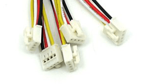
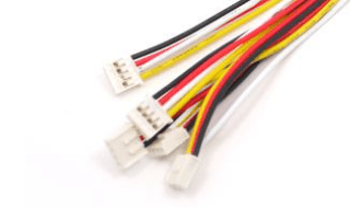
- Some connectors are latched (“buckled” – left below) and some are unlatched (“unbuckled” – right below).
- Latched/buckled are less likely to physically fit in Stemma JST PH sockets.
Electrow’s “crowtail” connectors seem to be physically the same as Grove, but I’ve not found details of the electrical specification. But again, the hints are that they are a proprietary form of Grove, so they might be compatible.
Sparkfun Qwiic
Sparkfun describe their Qwiic system here: https://www.sparkfun.com/qwiic
Points of note:
- Qwiic is 4-pin, 1.0mm pitch, I2C only.
- Qwiic and Stemma QT are essentially the same, but there are differences in terms of which end is expected to be doing level shifting, so read the Adafruit guide for details.
DFRobot Gravity
The DFRobot guide for Gravity is here: https://www.dfrobot.com/gravity, but to be honest I was struggling to find any technical specs, but from the previous guides (especially the Adafruit one), we can note:
- Gravity are JST PH 3 or 4 pin 2.0mm pitch connectors.
- 3-pin connectors support analog, digital and PWM.
- 4-pin connectors support UART or I2C.
- There is a high chance of compatibility with the physical I2C connectors provided logic levels are observed.
- HOWEVER – the wiring of Stemma and Gravity are apparently different even though the connectors are physically the same. Importantly, PWR/GND are swapped.
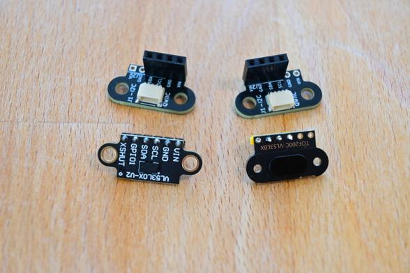
Duppa.net
But then there is the reason for my starting this post – finding the intelligent rotary encoders and LED rings provided by Duppa.net: https://www.duppa.net/product-category/i2c-devices/
These appear to have two different standards of their own:
- LED Ring: Molex Picoblade, 1.25mm pitch, 5-pin connectors.
- Encoder: JST XH 2.54mm pitch, 5-pin connectors.
Neither of these is directly compatible with each other or with any of the above, but it can be seen that both are essentially power, GND and I2C so it ought to be possible to build compatible converter cables.
The details of pinout and so on can be found in the GitHub repository here: https://github.com/Fattoresaimon?tab=repositories
Note, in some places online I’ve seen the 1.25mm pitch PicoBlade connectors listed erroneously as “JST 1.25” – but these don’t seem to exist on the official JST site.
Summary
This really has become a bit of an xkcd standards situation unfortunately, and I’ve not covered everything (Pimoroni have a different approach to I2C for example).
But hopefully now I’ve finally written it all down, I might be able to make some sense of it and actually start using them a bit more.
So I think the upshot of all the above is the following (the numbers are the pitch of the pins):
But I must admit I’m still not 100% sure I’ve got them all right…
Kevin