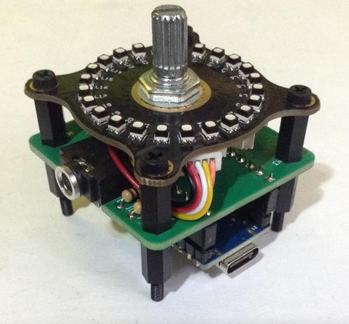
The designs are up for my single-knob, MIDI controller using a Duppa small RGB LED ring and in this case a Waveshare Zero RP2040 board.
https://diyelectromusic.com/2025/04/27/duppa-i2c-midi-controller-pcb-design/

The designs are up for my single-knob, MIDI controller using a Duppa small RGB LED ring and in this case a Waveshare Zero RP2040 board.
https://diyelectromusic.com/2025/04/27/duppa-i2c-midi-controller-pcb-design/
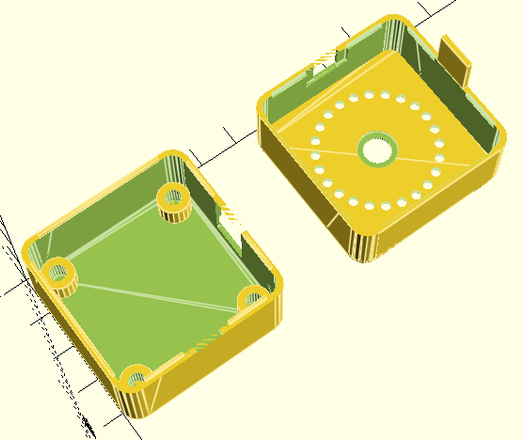
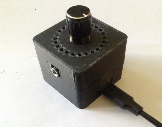
Duppa I2C MIDI Controller 3D Print Case
This is a simple 3D printed case for my Duppa I2C MIDI Controller PCB.
https://makertube.net/w/nf7u1sYBRRzj2TUBRduQC2
Warning! I strongly recommend using old or second hand equipment for your experiments. I am not responsible for any damage to expensive instruments!
If you are new to microcontrollers, see the Getting Started pages.
Parts list
OpenSCAD Design
This uses some of the techniques from my Raspberry Pi 2,3,4 A+/B+ Synth Cases to define a basic box, then some cut-outs, and then to split the box and add some overlapping “lips” for a snap-fit.
There a number of functions to achieve this, but some of them are just collecting together the others in the right sequence.
At the top level box_base, box_top and standoff (four times) actually builds the complete case.
In terms of assumptions about the build:
Notes on printing:
Errata/Improvements:
Closing Thoughts
This is a little tall, but I’m not sure what, in reality I could do about that. There might be some option for shrinking it a little, especially if the Waveshare Zero RP2040 is soldered directly to the PCB. But it would only save, maybe up to 6 mm in height, so it is probably not worth the effort.
But apart from that, this seems to have come out really well. The holes the LEDs I thought were perhaps a bit of a compromise, but actually they seem to work fine.
Kevin
Revisiting my Duppa LED Rings this time using Waveshare Zero format devices to support USB MIDI CC controllers.
https://diyelectromusic.com/2025/04/06/duppa-i2c-midi-controller-part-4/
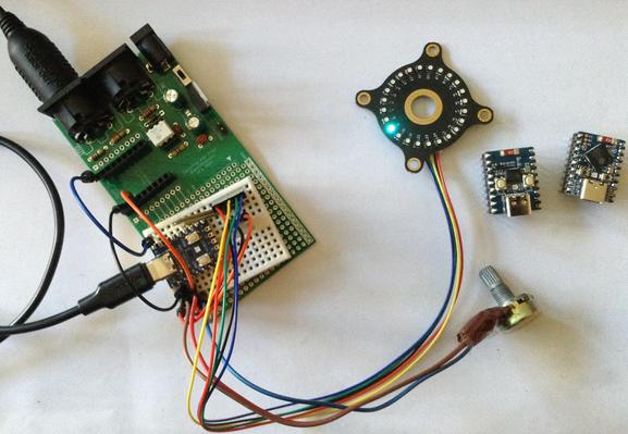
Duppa I2C MIDI Controller – Part 4
This is revisiting my Duppa I2C MIDI Controller this time using a Waveshare Zero format device.
Warning! I strongly recommend using old or second hand equipment for your experiments. I am not responsible for any damage to expensive instruments!
If you are new to Arduino, see the Getting Started pages.
Parts list
Waveshare Zero, Duppa LED Ring, Potentiometers
I’m planning on being able to use any Waveshare Zero format board that I have (so that includes ESP32-S3, ESP32-C3 and RP2040) with the Duppa Ring so that means finding common pins to support I2C.
From the various pinouts (see Waveshare Zero, Pimoroni Tiny, and Neopixels) I can see I can use two pins in the bottom right-hand (with the USB connector at the top) corner of the board.
I’ll also need an analog connection and potentially connecting RX/TX to MIDI.
The various pins I’ll be using are as follows:
PinFunctionESP32-S3ESP32-C3RP204015V2GND33V34ADCGP1GP0GP29/A313SCLGP10GP9GP514SDAGP11GP10GP417RXGP44GP20GP118TXGP43GP21GP0Note, I’m not using physical pins 11 and 12, even though they also support I2C, as for the RP2040, these are on I2C bus 1, not 0 (see note later).
As the Pimoroni Tiny2040 is largely compatible too, that could also be used, but it will be physical pins 11 and 12, corresponding to GP5 and GP4, and 15 and 16 for GP1, GP0 (RX,TX).
The LEDs on the LED ring are powered from 5V, which comes directly off the Waveshare Zero USB port. The logic “VIO” is powered from 3V3.
The Code
I2C LED Ring
As the I2C pins to be used are configurable, this means changing the Duppa example code (and any other Arduino code) to initialise the I2C bus on specific pins as follows:
Wire.begin(11,10); // SDA, SCL for ESP32-S3Using the ESP32 Arduino Core, there is a specific board entry for the Waveshare Zero ESP32-S3. There isn’t one for the ESP32-C3 so I just used “ESP32C3 Dev Module”.
I used the Arduino core for RP2040 from here rather than the official core: https://github.com/earlephilhower/arduino-pico
But the I2C initialisation is a little different.
Wire.setSDA(4);If I’d have been using GP6 and GP7, then these would have required the initialisation of Wire1 rather than Wire with the RP2040 core.
Note: to use the serial port once a sketch has been loaded onto the board, requires the following to be set (via the Arduino Tools menu):
USB CDC On Boot -> EnabledOnce again, I’ve soldered the jumpers on the LED ring to enable pull-ups and set the address for S1 and S5, so that has to be changed in the demo code too.
Analog Potentiometer
In terms of analog read, the ESP32 has a resolution of 0..4095 compared to the Arduino’s 0..1023, so that has to be taken into account when calculating the MIDI CC values.
To do this, the reading has to be divided by the ratio of Pot Range / 128.
int newpot = algpot.avgeAnalogRead(PIN_ALG) / ((MAX_POT_VALUE+1)/128);Serial MIDI
For these boards, the serial port has to be specified. There are different options depending on the board being used (more here).
To use the pins nominally designated as RX/TX on all of these boards, use:
// ESP32-S3 GP43,GP44 or ESP32-C3 GP20,GP21It is a quirk of the RP2040 Arduino core that UART0 appears on Serial1 and UART1 on Serial2. Serial0 does not exist but USB is Serial (more here).
Also, for the RP2040 the pins can be changed prior to calling MIDI.begin() if required as follows:
Serial1.setRX(rxpin);MIDI USB
I want to make this a fairly stand-alone MIDI USB device, so for the ESP32 and RP2040 this means using the TinyUSB stack. There is an Adafruit library for Arduino that supports both and also works with the Arduino MIDI Library. References:
I’ve cribbed most of the code from: https://github.com/adafruit/Adafruit_TinyUSB_Arduino/blob/master/examples/MIDI/midi_test/midi_test.ino
And added the appropriate parts to my own midiSetup() and midiLoop() functions.
MIDI USB – ESP32-S3
For this to work on the ESP32-S3, the board settings (via the Arduino Tools menu) need to be changed as follows:
USB CDC On Boot -> EnabledNaturally this means USB can’t be used for serial output anymore.
It also means that automatic sketch reset and download often didn’t work for me. It was quite normal to now have to use the BOOT and RESET buttons to get the ESP32 back into listening for a new sketch – not always, but also not uncommon. But this might be some serial port remapping weirdness that often occurs when the USB stack is running on the same microprocessor as the main code…
MIDI USB – RP2040
For the RP2040, the USB stack needs to be changed from the Pico SDK to TinyUSB, so in the Tools menu:
USB Stack -> Adafruit TinyUSBThere are some other RP2040 specific notes here, but I don’t believe they apply unless one is interested in rebuilding the core, default TinyUSB support directly.
USB MIDI – ESP32-C3
I don’t believe USB MIDI works on the ESP32-C3
Adafruit TinyUSB doesn’t seem to anyway and I haven’t looked into what the options might be yet.
Other Notes
I’ve left in all the conditional compilation from Duppa I2C MIDI Controller – Part 3 but for now am just working with potentiometer control.
Pretty much everything is configurable, but the most important config option is to specify the board at the top:
//#define WAVESHARE_ESP32S3I could probably auto detect from the build settings but for now, this will do.
Other options include GPIO pins, whether to include serial or USB MIDI (or both), and whether to enable MIDI THRU or not.
Closing Thoughts
This is the first go at getting my Duppa controller working on 3V3 Waveshare Zero format boards, and so far it looks pretty good.
For the ESP32-S3 and RP2040 being able to enable MIDI USB is particularly useful. I might see if I can support MIDI THRU across the interfaces, which might be handy for a built-in USB to serial MIDI converter, but for now MIDI THRU is on the same port only.
I’ve not tested this with encoders or the endless potentiometer, but in theory it ought to work. I’d have to add some conditional compilation for GPIO numbers if I want to keep the same physical pins again.
Kevin
#controlChange #duppa #endlessPotentiometer #esp32c3 #ESP32s3 #i2c #midi #potentiometer #rgbLed #rotaryEncoder #rp2040 #WaveshareZero


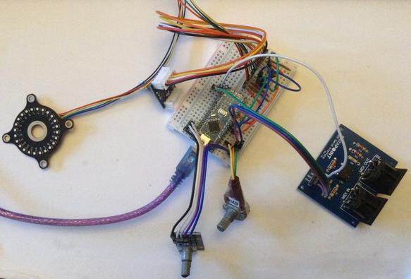
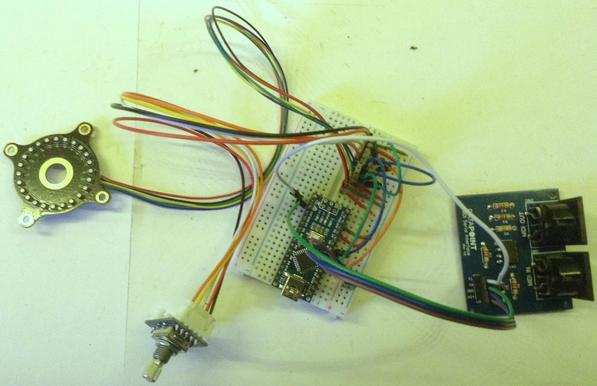
Duppa LED Ring Encoder MIDI CC Controller - Part 3

Adding options for potentiometer or plain rotary encoder control too.
Still waiting for my endless pots to be delivered :)
https://diyelectromusic.com/2025/03/18/duppa-i2c-midi-controller-part-3/
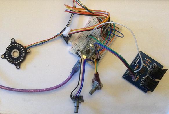
Duppa I2C MIDI Controller – Part 3
This is a follow up post to Part 2 expanding on the code and adding in some of the alternative control options I mentioned.
https://makertube.net/w/ncLFMqBwCUcrrM4r3mHJwd
Warning! I strongly recommend using old or second hand equipment for your experiments. I am not responsible for any damage to expensive instruments!
If you are new to Arduino, see the Getting Started pages.
Parts list
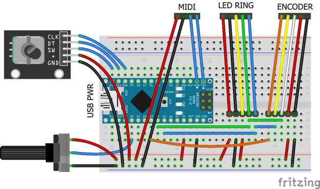
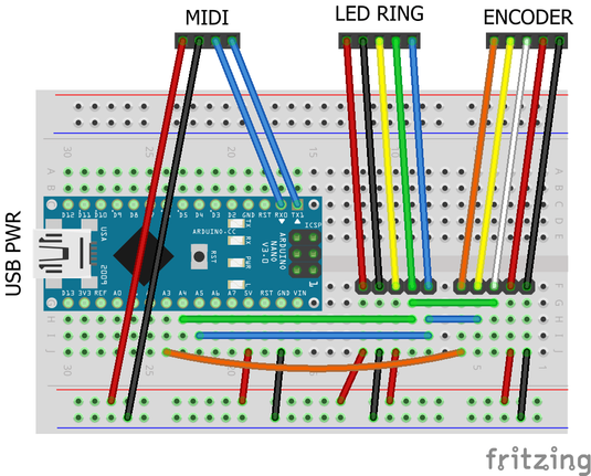
The Circuit
This circuit shows all three control options on the same diagram, but naturally use whichever one you require. There are the following three options:
In addition to the I2C LED Ring on A4, A5 (SDA, SCL) of course.
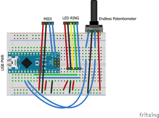
Here is a separate diagram for the endless potentiometer. I can be used alongside the above, but I’ve drawn it on its own for clarity.
Mine has the pins in the following order: Wiper A, GND, Wiper B, VCC.
The Code
This uses the code from Part 2 as a starting point and adds in some additional features.
The main aim is to add additional control options and then make them selectable in code. There are several definitions at the top of the file. One of them should be uncommented to enable that control option.
//#define CC_ENCODEREach control method will have some associated functions, but the interface will be hidden away behind these definitions and called from the main code, something like the following.
#ifdef CC_ENCODERIf that control option is not enabled, then it will just end up with the two empty functions.
Normal Potentiometer
This is fairly straightforward. I’m using the averaging technique I’ve mentioned before (details here) and include a counter so that the pot isn’t read on every scan, otherwise it slows down all other processing significantly.
The pot reading is scaled down to 7-bits from the default 10-bit value with a bitshift.
I’ve opted to have a jump if the CC value is updated over MIDI rather than anything more sophisticated, as that is probably the simplest.
All the same display options are available as used previously: one LED per CC; scaled to multiples of the ring size; or scaled to a single ring.
This works quite well with all of them, but probably makes most sense when the MIDI CC range is scaled to a single revolution of the LED ring.
CC_WRAP has no effect when used with a normal potentiometer, as the pot itself does not wrap around.
Rotary Encoder
This is using the same encoder library I’ve used before in my Arduino MIDI Rotary Encoder Controller. This makes the scanning code relatively straight forward.
I’ve refactored out the increment/decrement functions from the I2C encoder code into midiCCIncrement and midiCCDecrement, so these can now be used by both encoder options.
These encoder modules are often switched, but I’m not making use of the switch here.
Once again, all the same display options are available: one LED per CC; scaled to multiples of the ring size; or scaled to a single ring. CC_WRAP can be on or off.
Endless Potentiometer
There is a detailed discussion of how these work here: https://hackaday.io/project/171841-driveralgorithm-for-360-deg-endless-potentiometer
My initial thought was that I could just use one of the wipers, assuming it would go from 0 to full resistance and immediately back to zero, but they don’t – they gradually go from 0 to full resistance and then gradually back to 0 again. See the diagram in the above link.
This means that some processing is required to get a single reading out of them, so I ended up using a library from here:
Well actually, I ended up using the slight variant of the library as used on the “Ottopot” MIDI controller, which can be found here:
In my case I just dropping in the endlesspotentiometer.cpp/h files into my Arduino sketch (swapping any includes from <> to “” in the process). There was one reference to main.h that needed removing, and it required a definition of MAX_POT_VALUE which is 1023 for an Arduino Uno.
Then the code is fairly straight forward as the library is able to give an indication of direction and how much the pot has moved.
One thing to watch out for – I wanted this to be able to act on midiCC in a relative manner, replication the benefits of an encoder, but with a potentiometer, so I needed to know how much the pot had changed and then add that to the current midiCC value, rather than set it directly.
To do this I allowed midiCCIncrement/Decrement to take a parameter – how far to increase or decrease midiCC.
The core code for handling the endless pot was thus:
endpot.updateValues(epot1.avgeAnalogRead(PIN_EALG_1),I also turned the potentiometer averaging code into a class of its own so I could also use it here for both analog readings of the endless pot.
It took a bit of experimentation with the sensitivity and threshold settings and how they interacted with the frequency of reading, but I’ve ended up with something that seems to work ok for me.
Summary
Although at the start I said that one of the options should be commented out to select it, in reality, if the devices are all on separate IO pins, then actually they can all be enabled at once.
And it does seem to work pretty well, with all four methods: I2C encoder, plain encoder, potentiometer – all interacting as you might expect they would.
Closing Thoughts
I was quite surprised how usable everything was with all four input methods enabled. I probably wouldn’t recommend it for typical use, but it was a bit of fun.
It is particularly satisfying to sweep through the entire range using the pot with “one LED per CC” enabled, even though scaling a single ring to the potentiometers range makes more sense (to me).
At some point I will try to get several controls up and running.
Kevin
#arduinoNano #duppa #endlessPotentiometer #i2c #ifdef #midi #potentiometer #rgbLed #rotaryEncoder
An Arduino LED Ring MIDI CC controller using Duppa I2C Rotary Encoder and a 24-LED RGB LED ring.
https://diyelectromusic.com/2025/03/17/duppa-i2c-midi-controller-part-2/
Duppa I2C MIDI Controller – Part 2
This is a follow up post to Part 1 where I’m starting to look at MIDI applications and a range of control options.
Since posting the first part, I’ve stumbled across a rather excellent DIY MIDI controller that uses 8 of these Duppa LED rings and 8 endless potentiometers (which I hadn’t realised was even a thing!). It is a fantastic build, based on a Teensy and PlatformIO and I totally recommend going and taking a look. Read about it here: https://gerotakke.de/ottopot/.
https://makertube.net/w/2oKgvpZ29L2oExanSaUXjE
Warning! I strongly recommend using old or second hand equipment for your experiments. I am not responsible for any damage to expensive instruments!
If you are new to Arduino, see the Getting Started pages.
Parts list
The Circuit
I eventually want to include various options for controlling the ring and MIDI:
I don’t have any endless potentiometers yet, they are something I’ve only recently found exist, but I’ll post again when I get a chance to try them!
The required connections, naturally, are quite different for each case:
In this first post, I’m just looking at the same Duppa I2C Encoder and LED Ring that I used in Part 1 but am adding a 5V compatible MIDI module.
The Code
Once again, this is using the Duppa Arduino library: https://github.com/Fattoresaimon/ArduinoDuPPaLib/
CC, Pots, Encoders…
The biggest issue I find with attempting to develop a MIDI CC controller is where is the authoritative definition of what the CC value actually is? What do I mean by that? Well we have the value in the synthesizer, defined on power up or via the on-board controls. And then we have the setting in the external MIDI controller. Until the MIDI controller sends an updated value to the synth, these will be different. And if the value on the synth changes locally, e.g. using knobs or controls on the synth, then they will be out of sync.
I’ve not found an easy answer to this, but what I’m planning is having the CC controller receive MIDI CC messages as well as send them. This means that if the CC value is changed directly on the synth, if the synth transmits that over MIDI, then it will be received by the external controller which can update its own value accordingly.
One problem with this is that there are two types of hardware controller: relative or absolute.
A rotary encoder is a relative controller – it turns in a direction and the value will increase or decrease accordingly. If the internal knowledge of the CC value changes, the encoder will just continue to increase of decrease from that new value instead.
A potentiometer is (usually) an absolute controller – it turns and has a value. If the internal knowledge of the CC value changes, then unless you have a motorised potentiometer, it will still be in the same place so on turning there will be a jump in value from the stored value to the new setting of the potentiometer.
One option to deal with absolute values is to have the new position value only become relevant once the turning “catches up” with the internal value and the starts adjusting it from that point onwards. But this can create a disjoint between the user experience of turning the knob and it actually changing anything. But on the plus side, absolute values are “remembered” when powered off – providing the knobs are left in the same place.
I’m hoping to use the encoders as a pseudo potentiometer. But it isn’t going to be possible to have a complete rotation considered the same as a full sweep of a potentiometer, as that will be down to the number of “detents” per rotation and that won’t be anything like enough to support 128 MIDI CC values. But I do plan to indicate the value by LEDS, and use those to indicate the position in the full sweep. This will allow the starting point to change if a CC message is received.
One solution to this problem, and that used by the Ottopot controller mentioned at the start, is to use an endless potentiometer. This not-only allows a variable starting position, but it also represents a full-sweep of values with a single turn as per a simple potentiometer.
So when I get hold of some of those I’ll come back to revisit this code.
For this first version there is code for the I2C encoder implemented using the following functions:
These are based on the code I used in Part 1. The increment and decrement functions act on a global “midiCC” directly, which stores the CC value to use using the range of a single MIDI “byte” 0 to 127. There is a compilation option to allow wrapping around (between 0 and 127) or not.
MIDI Handler
The Arduino MIDI library is used for both send and receive and all MIDI functionality is wrapped up in the following functions:
There are a few additional functions to give an optional LED indication of MIDI activity. Within the MIDI loop the midiCC value is checked and if it has changed then a MIDI control change message is transmitted:
void midiLoop() {There is an option to have software MIDI THRU enabled and this is handled as part of the MIDI.read() call. On setup midiControlChange() is installed as a handler function for MIDI CC messages and if the correct CC message is received on the correct MIDI channel then the midiCC value is updated directly.
One consequence of using midiCC directly and it being changed by either the encoder or from MIDI is that any change will also trigger the sending of the CC value out too.
This means that if MIDI THRU is enabled and a MIDI CC value is sent to the Arduino then it will almost certainly be sent back over MIDI twice – once as part of the THRU handling, and once as a consequence of it having changed the Arduino’s stored midiCC value.
LED Ring Indicator
The simplest implementation will be to scale the 24 LEDs of the ring to the 128 MIDI values and light up the LED that best represents the chosen value.
An alternative is to use one LED per MIDI CC value and allow the ring to loop round, possibly in a different colour. For 128 values across 24 LEDs this means there will be five full circles of the ring plus 8 more.
I’ve also provided the option to scale the MIDI CC values to a multiple of the LED ring so that the full MIDI 0..127 range wraps around back to 0 back at the start of the ring.
In the following, scalemax is the largest multiple of NUM_LEDS that will fit in 128, then the midiCC value is scaled to that new range and then used in the rest of the LED calculation.
int scalemax = 128 - 128 % NUM_LEDS;One quirk to note is that the LEDs are numbered anti-clockwise, so at some point I’ll have to reverse the LED number when it comes to presenting an increasing CC value as a clockwise changing display.
I’d also like to have a bit of a lazy, dragging LED change, so I want to implement something that fades illuminated LEDs out as the value changes, leaving some kind of “tail” as the LED moves.
To do this, I’ve used an array to store the colour value used for any illuminated LEDs and then at regular intervals that colour is updated to fade back to OFF.
I’ve implemented a relatively simple fade – basically each of the R, G and B components of the colour is bit-shifted to the right by 1 on each “scan”. This has the effect of continually dividing the colour value by 2 until it reaches 0. The only thing to watch out for is that I don’t do this for the current illuminated LED.
Also note that I only pull out the most significant 7 bits of each 8 bit value (by & 0xFE) so that the shift doesn’t map the least significant bit of one value down into the next colour.
for (int i=0; i<NUM_LEDS; i++) {All the LED handling is wrapped up in the following functions:
The last function is responsible for swapping the LED numbers around to make them go clockwise. It isn’t as simple as doing NUMLEDS – led as I still want the first LED to be at “12 o’clock”, hence the function to return the correct index.
Closing Thoughts
I am so pleased with that lazy LED change effect.
Having so many turns of the encoder isn’t particularly practical at the moment, but it does work. It is certainly good to have a few configuration options – especially the option to wrap around, as it takes quite a few turns to get from 0 to 127.
In a follow up post I’ll take a look at some of the other options, and when I get my endless encoders in the post that will definitely get a mention too.
I also want to wrap up the existing code somehow to allow for several LED CC controls if required and some kind of box might also be nice.
Kevin

Duppa LED Ring Encoder MIDI CC Controller


