Arduino and AY-3-8910
I’ve had some AY-3-8910 programmable sound generators for a while and planned to do something with them, but they’ve sat in the “to think about” box for a while. But recently getting hold of the WhyEm sound card for the RC2014 has re-awakened my interest.
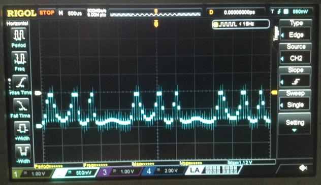
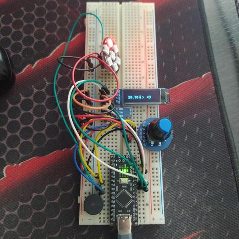
This is some “first looks” experiments with the AY-3-8910 and an Arduino.
- Part 1 – Getting started and looking at playing YM files.
- Part 2 – Adding basic MIDI control.
- Part 3 – Basic experiments with direct digital synthesis.
- Part 4 – Using the AY-3-8910 as a 4-bit DAC for Mozzi.
https://makertube.net/w/26yAj7wAzZwCsFoBkJpZs2
Warning! I strongly recommend using old or second hand equipment for your experiments. I am not responsible for any damage to expensive instruments!
These are the key tutorials for the main concepts used in this project:
If you are new to Arduino, see the Getting Started pages.
Parts list
- Arduino Uno
- AY-3-8910 chip
- Either GadgetReboot’s PCB or patch using solderless breadboard or prototyping boards.
The AY-3-8910 PSG
The AY-3-8910 programmable sound generator is quite an iconic chip of its time. Not as popular maybe as the SID used in the Commodore 64, but still pretty widespread use in 8-bit computers of the time and apparently a number of arcade machines too.
There are a number of “compatible” chips, including the Yamaha YM2149. There is also the AY-3-8912 which is the same as the 8910 but without one of the general purpose IO ports, which take no part in the sound generation.
I’m not going to go into the details of the device itself, for that I’ll refer to the following resources:
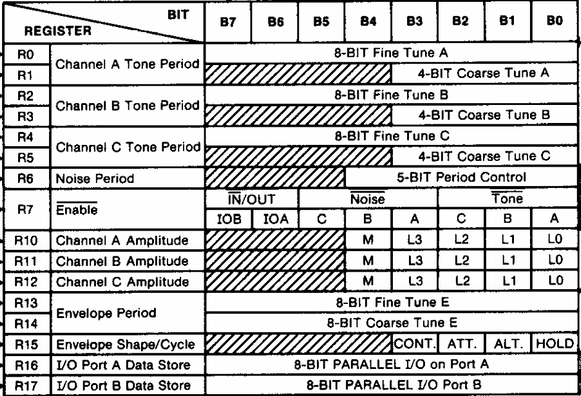
The summary of the specification though is as follows:
- Three square wave output channels.
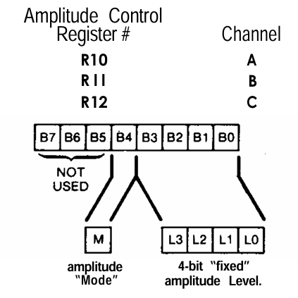
- Global AD envelope generator, with a selection of fixed envelopes.
- Noise generator an option on the channels.
- Mixer.
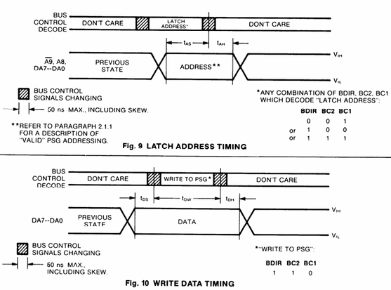
There is an 8-bit data register interface to the chip along with three control signals (BDIR, BC1 and BC2).
I should point out that it isn’t possible to buy new AY-3-8910 or YM2419 chips these days, so any that can be found online are almost certainly reclaimed from older hardware. These may or may not work reliably, but it will be a bit of a lottery.
There is a lot of discussion about the issue here: http://blog.tynemouthsoftware.co.uk/2023/01/testing-ay-3-8910-ym2149-sound-card-for-rc2014-and-minstrel-4D.html
This is why RC2014 eventually went with the “Why Emulator” approach: https://rc2014.co.uk/modules/why-em-ulator-sound-module/
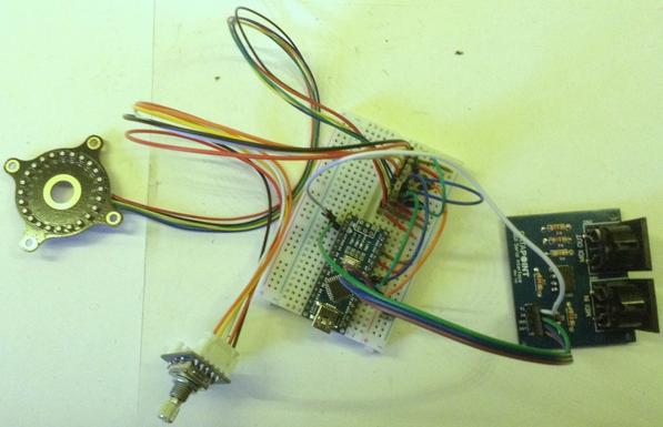
Hardware
For once, I’m using someone else’s design for my initial messing about. There is a schematic and some hardware built on a protoboard shown in the Arduino YM3891x library here: https://github.com/Andy4495/AY3891x/tree/main/extras/hardware
But there is a PCB that was designed by GadgetReboot here: https://github.com/GadgetReboot/AY-3-8910. This can be ordered directly from PCBWay and so that is what I’ve used.
The only thing to watch out for, is that D2/D3 are reversed compared to the protoboard hardware. So whilst all other pin definitions in the library examples are fine, D2 and D3 need to be swapped to use them with the PCB.
I also didn’t bother to add the power LED (and R5), the toggle switch or the additional header pins.
The full pinout interface from the Arduino to the AY-3-8910 is as follows:
AY-3-8910ArduinoDA0-DA7D2-D8, A3BC1A0BC2A1BDIRA2CLOCKD9/RESETA4 (not used in the library)
The most critical one from a re-use point of view is the clock as the code uses the ATmega328P hardware Timer 1 to output a 50% duty cycle PWM signal on output OC1A (D9) to generate the 1MHz clock required by the AY-3-8910.
Using a different microcontroller will mean re-writing this part of the code for a suitable replacement timer.
The PCB also has the following Arduino GPIO pin use:
- D0/D1 – UART pin header
- D10-D13 – SD card pin header
- A4 – /RESET of the AY-3-8910 but doesn’t appear to be required to use the library.
The AY-3-8910 is powered from the +5V from the Arduino. VIN for the Arduino is not connected, so USB power is assumed.
The Code
Taking the “AY3891x_EX3_Simple_Tone” example as a starting point, the following line needs updating as shown below:
// Original line
AY3891x psg( 17, 8, 7, 6, 5, 4, 2, 3, 16, 15, 14);
// Required for use with the PCB
AY3891x psg( 17, 8, 7, 6, 5, 4, 3, 2, 16, 15, 14);
This is using the “lesser number of pins” constructor, which assumes that the A8, A9, /RESET and CLOCK pins of the AY-3-8910 are not managed by the library. There is a more complete constructor to define the additional pins if required. There is a good description of how the AY-3-8910 interface works in the main source code: https://github.com/Andy4495/AY3891x/blob/main/src/AY3891x.cpp
I also switched any Serial.begin() statements to use 9600 baud for preference too.
With these changes, the simple tone example just works, as does the “AY3891x_EX8_Check_Orig_or_Clone”, which tells me I have an AY-3-8910 rather than a YM2149.
But what I really wanted was to play one of the tunes from a game I remembered. My first introduction to AY-3-8910 music was the 128K Spectrum version of The Neverending Story. This was one of the two games that came bundled with the original machine, and for someone used to the 48K beeps and boops it was an amazing upgrade.
Unfortunately I don’t seem able at present to find a “YM” file version of that tune to play, so instead I turned to a David Whittaker classic – “Glider Rider”. The “YM Jukebox” GitHub repository has a whole pile of YM files ready to use here: https://github.com/nguillaumin/ym-jukebox/tree/master/data/David%20Whittaker
There are (I believe) two key ways to get “chiptunes” for the AY-3-8910. A YM file is a stream of the register values sent to the chip to direct the sound generation. With one of these files, it is simply a case of turning these values into a C array and it can be included in an Arduino sketch (there are several steps required, see below, but it is all doable).
Another common way to get tunes is an “AY” file. As I understand things these are the actual Z80 assembler instructions required to drive the AY-3-8910 chip, so extracting the required data for use on another system is not so easy. These are really designed to be used on the original systems or via emulation.
To produce an Arduino source code file from a YM file requires the following steps (described here: https://github.com/Andy4495/AY3891x/tree/main/extras/tools):
python decoder.py GliderRider.ym force_interleaved
python bin2c14.py outputfile > chiptunes.h
- Take the resulting const PROGMEM structure into the “chiptunes.h” file of the “AY3891x_EX6_Chiptunes_Flash” example sketch.
Note that due to the memory limitations of the Arduino Nano, the resulting C structure for the tune will have to be cut-off at around 2000 lines, but be sure to leave the termnating part of the structure:
const byte PROGMEM psg_data[] = {
0x6C,0x07,0x7C,0x07,0x7C,0x07,0x17,0x31,0x0F,0x00,0x00,0x00,0x00,0x20,
0x6C,0x07,0x7C,0x07,0x7C,0x07,0x1F,0x31,0x0D,0x00,0x00,0x00,0x00,0x00,
....
0x7C,0x07,0xBE,0x03,0x58,0x02,0x01,0x31,0x09,0x0E,0x00,0x00,0x00,0x00,
};
If there are build errors, then it might be because the structure is still too long. 2000 lines fits for me using around 97% of the programme memory of the Arduino Nano.
If full (longer) tunes are required, then the PCB has the option to hook up to an SD card and longer files can be stored there.
YM Files
Here is a little more detail about the above process required to get a YM file into C code, mostly for my own reference (the above links all talk about it pretty well tbh).
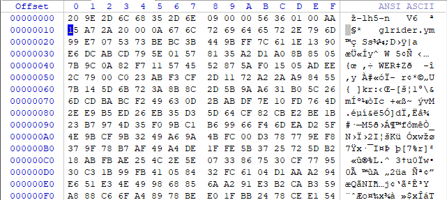
Step 1: A downloaded YM File is usually actually compressed using LHA. 7Zip can open these files and save the extracted version ready for step 2.
Here is the difference of the start of the files shown using a hex editor. Notice the “-lh5-” header near the start showing that this is a LHA compressed file, and a filename associated with the uncompressed version, in this case glrider.ym.
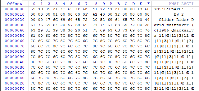
Uncompressed:
We can now clearly see he header information including the file identifier “YM5!” along with title, author and copyright information in comment fields.
The AU3891x library goes on to explain: “This uncompressed binary file has the audio programming registers stored in a non-interleaved format for more efficient compression. These values now need to be interleaved for more efficient playback.”
We can find more details of the YM file format here, in the words of the creator of the format, Arnaud Carré, directly: https://www.lynn3686.com/ym3456_tidy.html
A music-file is composed of YM2149 registers generated by the
original play-routine for each 50th seconds. As the YM2149 has 14 registers 8 bits each, that means 14 bytes for 1/50 second, so 700 bytes for one second of soundchip.
When I convert an ATARI music, I play the music on the ATARI, and I
store YM2149 registers set each 1/50sec (Vertical Blank time, VBL) in a big file as follow:
VBL1:
store reg0,reg1,reg2,...,reg12,reg13 (14 regs)
VBL2:
store reg0,reg1,reg2,...,reg12,reg13 (14 regs)
...
VBLn:
store reg0,reg1,reg2,...,reg12,reg13 (14 regs)
The problem is that is takes a lot of disk-space. Just count: A 10
minutes song will take 420000 bytes on disk. But don't panic, the music are compressed with LHARC method (using LHA program from Haruyasu Yoshizaki). To reach best compression ratio, I store registers in a different order:
VBL1 reg0, VBL2 reg0, VBL3 reg0 .... VBLn reg0
VBL1 reg1, VBL2 reg1, VBL3 reg1 .... VBLn reg1
...
VBL1 reg14,VBL2 reg14,VBL3 reg14.... VBLn reg14
Hence the “interleaved” format discussed previously. So looking at the file itself, specifically for YM5 it has the following format:
Offset Size Type Comment
0 4 DWORD ID of YM5 format. ('YM5!')
4 8 string[8] Check String ('LeOnArD!')
12 4 DWORD Nb of valid VBL of the file.
16 4 DWORD Song attributes (see below)
20 2 WORD Nb of digi-drum sample (can be 0)
22 4 DWORD YM2149 External frequency in Hz (ex:2000000 for ATARI-ST version, 1000000 for AMSTRAD CPC)
26 2 WORD Player frequency in Hz (Ex: 50Hz for almost player)
28 4 DWORD Vbl number to loop the song. (0 is default)
32 2 WORD Size (in bytes) of futur additinal data. (must be 0 for the moment)
So we can see this playing out from the above file:
00000: 59 4D 35 21 = "YM5!"
00004: 4C 65 4F 6E 41 72 44 21 = "LeOnArD!"
0000C: 00 00 13 60 = Number of frames: 4960
00010: 00 00 00 01 = Attributes:
b0: Set if Interleaved data block.
b1: Set if the digi-drum samples are signed data.
b2: Set if the digidrum is already in ST 4 bits format.
00014: 00 00 = No digidrum samples
00016: 00 0F 42 40 = External frequency 1MHz
0001A: 00 32 = Player frequency 50Hz
0001C: 00 00 00 00 = Number of loops for the song: 0
00020: 00 00
This header is then followed by:
For each digidrum sample:
4 DWORD sample size
nnnn BYTES sample data (8bits per sample)
NT-String Name of the song.
NT-String Name of the author.
NT-String Comments (YM file converter ?!)
All YM2149 registers.
4 DWORD End-File check. ('End!')
Which again we can now see in the uncompressed file:
(no digidrum samples)
00022: 476C6964657220526964657200 = "Glider Rider"
0002E: 4461766964205768697474616B657200 = "David Whittaker"
0003E: 2863293139383620517569636B73696C766100 = "(c)1986 Quicksilva"
00052: 6C6C7C8C... = 4960 values for reg0
013B2: 07070707... = 4960 values for reg1
...
0FC32: 02000000... = 4960 values for reg13
10F92: 00000000... = 2x4960 additional sets of values
13652: 45 6E 64 21 = "End!"
Curiously there seems to be data for 16 registers, which I guess would allow the inclusion of the two GPIO ports as well as the sound generation registers.
So to turn this into a stream of register values to send to the AY-3-8910 at a rate of 50Hz requires take the same “VBL” value for each register in turn and de-interleaving it.
This is the output from the decoder.py file as it processes the above:
Attempting to read file at glrider.ym...
YM5! format file detected based on first four bytes of file...
4960
File is interleaved...
Song title: Glider Rider
Author: David Whittaker
Comments: (c)1986 Quicksilva
Data length is 79360 bytes...
Song length is 4960 frames...
Deinterleaving...
Register 0: 0x6c 01101100
Register 1: 0x07 00000111
Register 2: 0x7c 01111100
Register 3: 0x07 00000111
Register 4: 0x7c 01111100
Register 5: 0x07 00000111
Register 6: 0x17 00010111
Register 7: 0x31 00110001
Register 8: 0x0f 00001111
Register 9: 0x00 00000000
Register 10: 0x00 00000000
Register 11: 0x00 00000000
Register 12: 0x00 00000000
Register 13: 0x20 00100000
==Frame#00000/04959======
Register 0: 0x6c 01101100
Register 1: 0x07 00000111
Register 2: 0x7c 01111100
Register 3: 0x07 00000111
Register 4: 0x7c 01111100
Register 5: 0x07 00000111
Register 6: 0x1f 00011111
Register 7: 0x31 00110001
Register 8: 0x0d 00001101
Register 9: 0x00 00000000
Register 10: 0x00 00000000
Register 11: 0x00 00000000
Register 12: 0x00 00000000
Register 13: 0x00 00000000
==Frame#00001/04959======
...
Register 0: 0x7c 01111100
Register 1: 0x07 00000111
Register 2: 0x54 01010100
Register 3: 0x00 00000000
Register 4: 0x0f 00001111
Register 5: 0x03 00000011
Register 6: 0x01 00000001
Register 7: 0x31 00110001
Register 8: 0x07 00000111
Register 9: 0x0c 00001100
Register 10: 0x0d 00001101
Register 11: 0x00 00000000
Register 12: 0x00 00000000
Register 13: 0x00 00000000
==Frame#04959/04959======
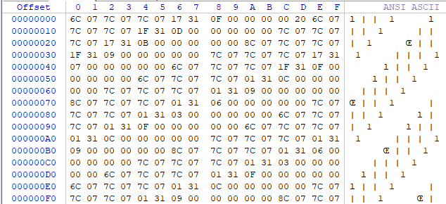
Notice that this is only pulling out the 14 sound generating registers. We can see this in the resultant de-interleaved file.
We can see tha tthe first two values correspond to the first items for reg0 and reg1: 6C and 07 and finish the 14 values with 20 before starting on the new set of 14 register values (again starting with 6C and 07 in this case).
The final step turns the above data stream into a C header file mentioned above.
To play the file thus requires the following algorithm:
Every 50Hz:
Read the next 14 register values from the data
Write all 14 register values out to the AY-3-8910
Closing Thoughts
I’ve really not done very much myself this time. The PCB was from GadgetReboot. The library from Andy4495. The tune data provided by the YM jukebox and all other scripts and bits of the process were available online.
Now I need to decide what I’d like to do with all this.
Kevin
#arduinoNano #ay38910 #chiptunes