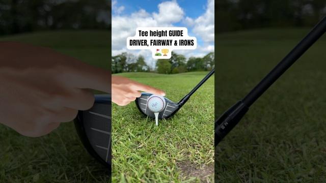
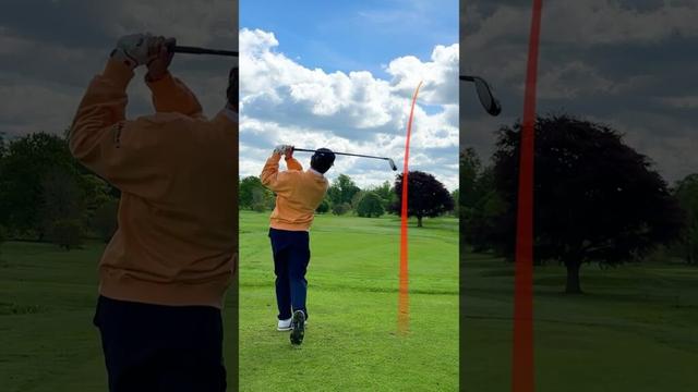
How do you make the Dutch Giant look tiny? Stand him next to Wadlow.

https://www.youtube.com/shorts/GjodmPppqMo

#Height #People

The Dutch Giant (7’2”) VS The Tallest Man Who Ever Lived 😳(8’11”) (Robert Wadlow)

YouTube

Atari 2600 Cartridge Emulation – Part 2

Following on from my previous post: Atari 2600 Cartridge Emulation in this post I start to look at how to build a custom Atari 2600 ROM itself.

I’ve spent a bit of time pouring over the assembler for the Atari photo frame app and I can’t see any obvious places where the byte ordering might go awry, so I’ve decided to rebuild the ROM itself from scratch just to be sure that what is in the binary file is what I’m expecting.

It would be nice to solve the issue I was seeing, but this will also hopefully serve as a useful introduction to writing and building code for the Atari 2600.

Spoilers: I think it was the timing between the PAL Atari and the Pico’s ROM routines. Adjusting the Pico code seems to solve it.

Atari 2600 Development

There is a brilliant introductory tutorial for Atari 2600 development here: https://www.randomterrain.com/atari-2600-memories-tutorial-andrew-davie-01.html

The basic steps are:

  • Install the tool chain and programming environment. This is based on the DASM cross-platform assembler.
  • Install an emulator – Stella is the emulator of choice.
  • Grab any relevant documentation and references:
    • Stella Programmer’s Guide
    • AtariAge
  • Build and load the code.

Installing the Toolchain

I’m using my Ubuntu installation, so after a quick update of the core libraries, I installed DASM.

$ sudo apt-get update
$ sudo apt-get upgrade
$ sudo apt-get install dasm
$ wget https://raw.githubusercontent.com/johnidm/asm-atari-2600/master/vcs.h
$ wget https://raw.githubusercontent.com/johnidm/asm-atari-2600/master/macro.h

As well as installing DASM the Atari 2600 environment and macro files are required from here: https://github.com/johnidm/asm-atari-2600

At this point, to build an Atari 2600 ROM binary file requires the following:

$ dasm myfile.asm -f3 -omyfile.bin -lmyfile.lst

To get this into picoROM then requires some additional processing. There is a python script that will take a binary file and churn out a series of rom_contents[n] = val; statements which can then be pasted into the pico_rom.c file.

$ python3 translate_bin2rom.py myfile.bin > newrom.c

The contents of newrom.c will now have statements for rom_contents[0] through to rom_contents[4095] which need to replace those already in setup_rom_contents().

Return to the Photo Frame

I really wanted to figure out what was going on with the photo frame application from part 1. My initial suspicions are that it might be related to the PAL/NTSC difference, so that is the starting point.

What are the main differences? The refresh frame rate and number of lines scanned per frame:

PALNTSCFrame Rate50 Hz60 HzNumber of Scan Lines625525

I know from having read “Racing the Beam” how critical timing is to driving the display and interspersing logic and display code. The “Atari 2600 Programming for Newbies” Guide states it thus:

“But from the ‘2600 point of view, the difference in frequency (50Hz vs. 60Hz) and resolution (625 scanlines vs. 525 scanlines) is important—very important—because it is the PROGRAMMER who has to control the data going to the TV. It is not done by the ‘2600 (!!)—the ‘2600 only generates a signal for a single scanline.”

“This is completely at odds with how all other consoles work, and what makes programming the ‘2600 so much ‘fun’. Not only does the programmer have to worry about game mechanics—but he or she also has to worry about what the TV is doing (for example, what scanline it is drawing, and when it needs to start a new image, etc.).”

Another complication is that the displays are interlaced, that is half the scanlines are displayed first, then the rest. By displaying every other line, persistence of vision means that the fact that it takes time to go from top to bottom for each frame is largely hidden from view.

But the consequence of this is that the actual display frame rate, when interlacing is taken into account, is 25 Hz for PAL and 30 Hz for NTSC.

The TIA in the 2600 runs with a pixel clock of 3.58MHz and the 6502 runs at 1/3 that, so there is one CPU cycle per three pixels. I think this is universal across both PAL and NTSC. According to this guide there are 228 pixel clock counts for a horizontal line, which I believe means 1 line will take around 64uS.

A full NTSC frame would thus be around 262*64 = 16.8 mS which gives us the 60Hz refresh rate. A full PAL frame would be around 312*64 = 19.9mS which gives us the 50Hz refresh rate.

There are many tricks associated with squeezing the most out of the hardware and a key technique relates to changing the registers that support graphics processing “on the fly” – whilst the TV scan is actually happening – hence “Racing the Beam” in the title of the book.

The 48-Pixel Trick

One of those tricks used by the photo frame application is the “48 pixel trick” which is described in the following:

I don’t know enough about 2600 programming yet to describe it in detail, but I believe the key idea is something like the following:

  • It takes time to update the graphics registers to write to the display. There are registers for “player 0” and “player 1” sprites (not to be confused with “play field” registers).
  • But there are some tricks to “preload” the information and have it queued up ready to display quickly using either CPU registers or mechanisms built into the Atari’s TIA device.
  • There are some techniques for interleaving the P0/P1 data and repeating it across the scanline.
  • Key to this are the following:
    • VDEL – “vertical delay” which enables a kind of “shadow” graphics register as I understand things.
    • NUSIZ – “Number/Size Player/Missile” which can be used to indicate a number of copies of each sprite.

There is a great description from the Retrochallenge write-up:

“So, finally, we come to meet the famous 6-Digits Score Display, also known as Big Sprites, or 48-Pixel Display. It’s the best we can do in “high” resolution on the Atari 2600: 48 pixels in a row, composed of the two player sprites (8 pixels each) replicated 3 times at an offset of 16 pixels (“close”). The two sprites will be mended together, forming a continous strip of 48 pixels (8 × 6). Nothing out of the ordinary, since the VCS and its TIA chip provide for that. Our job is now to change the bit-patterns for the two sprites on the fly, 4 times, just-in-time, with perfect cycle count.”

It goes on to show how unfortunately updating the registers is just slightly too long compared to the “beam time”, but by clever use of the VDEL and the “shadow” registers, it can all be speeded up by preloading as much as possible.

There is one confusing property to note. Writing to GPR0 will trigger an update to the display from the shadow register for GPR1 and vice versa. this creates for a very confused sequence of updates, but does allow for time-critical updating of the display in sequence with “the beam”.

So looking at the photo frame display code, we can add the following annotations to the main display loop.

; VBLANK
WaitVBlank
lda INTIM
bne WaitVBlank
sta WSYNC ; Wait for the next horizontal sync
sta VBLANK ; Do vertical blanking period

ldy #HEIGHT
sty ImageHeightCnt ; Initialises and stores the image height counter
BigGraphicLoop ;Cycles(sum)[Pixels]
sta WSYNC ; 3 (0) [0] ; Hor Sync starts the process
lda sprite0 ; 4 (4) [12] ; We have 68 clock counts before things display
sta GRP0 ; 3 (7) [21] ; byte0 -> GRP0
lda sprite0 ; 4 (11) [33]
sta GRP1 ; 3 (14) [42] ; byte1 -> GRP1; byte0 -> GRP0A
lda sprite0 ; 4 (18) [54]
sta GRP0 ; 3 (21) [63] ; byte2 -> GRP0; byte1 -> GRP1A
lda sprite0 ; 4 (25*) [75]
tax ; 2 (27) [81] ; byte3 -> X
lda sprite0 ; 4 (31) [93]
sta Temp ; 3 (34) [102] ; byte4 -> Temp
lda sprite0 ; 4 (38) [114] ; byte5 -> A
ldy Temp ; 3 (41) [123] ; byte4 -> Y; at start of px 123 GRP0A (byte0) -> TV

stx GRP1 ; 3 (44) [132] ; byte3 -> GRP1; byte2 -> GRP0A; GRP1A (byte1) -> TV
sty GRP0 ; 3 (47) [141] ; byte4 -> GRP0; byte3 -> GRP1A; GRP0A (byte2) -> TV
sta GRP1 ; 3 (50) [150] ; byte5 -> GRP1; byte4 -> GRP0A; GRP1A (byte3) -> TV
sta GRP0 ; 3 (53) [159] ; dummy -> GRP0; byte5 -> GRP1A; GRP0A (byte4) -> TV
dec ImageHeightCnt ; 5 (58) [174] ; ; GRP1A (byte5) -> TV
ldy ImageHeightCnt ; 3 (61) [183]
bpl BigGraphicLoop ; 2/3 (64) [192]

lda #0 ; Clear registers
sta GRP1
sta GRP0
sta GRP1

ldx #(192-HEIGHT) ; Skip required number of lines for a full frame
VSLoop ; 192 for NTSC, 242 for PAL
sta WSYNC
dex
bne VSLoop

SetupOS ; Overscan (bottom of the display)
lda #36
sta TIM64T

; Overscan
WaitOverscan
lda INTIM
bne WaitOverscan

Why does the TV display only start at pixel position 123? That is determined by the call to SetHorizPos, as will be described next.

One other point of note. This code reads out 6 bytes, giving us the 48 pixels. But the image is a 64 pixel wide image. To solve this, a second graphics loop is performed on the interlaced scan for the final 16 pixels.

Setting the Horizontal Position

The SetHorizPos function needs a little explanation.

From the Stella Programmers Guide, section 7.0:

“The horizontal position of each object is set by writing to its associated reset register (RESP0, RESP1, RESM0, RESM1, RESBL) which are all “strobe” registers (they trigger their function as soon as they are addressed). That causes the object to be positioned wherever the electron bean was in its sweep across the screen when the register was reset. for example, if the electron beam was 60 color clocks into a scan line when RESP0 was written to, player 0 would be positioned 60 color clocks “in” on the next scan line. Whether or not P0 is actually drawn on the screen is a function of the data in the GP0 register, but if it were drawn, it would show up at 60. Resets to these registers anywhere during horizontal blanking will position objects at the left edge of the screen (color clock 0). Since there are 3 color clocks per machine cycle, and it can take up to 5 machine cycles to write the register, the programmer is confined to positioning the objects at 15 color clock intervals across the screen. This “course” positioning is “fine tuned” by the Horizontal Motion, explained in section 8.0.”

This is what is implemented in the SetHorizPos function. There is a great discussion of how it works here: https://forums.atariage.com/topic/308513-a-working-horizontal-positioning-routine/ and more detailed explanation here: https://bumbershootsoft.wordpress.com/2018/08/30/an-arbitrary-sprite-positioning-routine-for-the-atari-2600/

On entry, A = required x-coordinate and X is the reset register to work with where X=0 for RESP0, X=1 for RESP1.

SetHorizPos
sta WSYNC ; start a new line
bit 0 ; waste 3 cycles
sec ; set carry flag
DivideLoop
sbc #15 ; subtract 15
bcs DivideLoop ; branch until negative
eor #7 ; calculate fine offset
asl
asl
asl
asl
sta RESP0,x ; fix coarse position
sta HMP0,x ; set fine offset
rts ; return to caller

The basic idea is to wait until the scanning reaches the required point and then use the RESPx register to say “put sprite here”. The minimum loop for scanning will take up 15 pixels of time, which is also the time taken to subtract 15 from the required value and continually branch until negative, hence the use of the otherwise apparently magic number 15 above.

As the granularity is fixed at 15 pixels, the HMPx registers are used for further fine adjustment.

This is all spelled out in the Newbies tutorial here: https://www.randomterrain.com/atari-2600-memories-tutorial-andrew-davie-22.html

Vertical Blank Timing

One other trick for getting the vertical timing correct is to use the TIMxxx and INTIM registers. The TIMxxx registers are timers which can be checked using INTIM. TIM64T counts 64 cycle blocks and is used here as follows:

VERTICAL_SYNC
lda #44
sta TIM64T

... code ...

WaitVBlank
lda INTIM
bne WaitVBlank

... next block ...

This (and similar other sections) will ensure the next block of code is properly synchronised to the vertical scan requirements.

In this case, it is accounting for the 37 scanlines that form the top vertical blank:

  • 37 x 76 CPU instructions = 2812 CPU cycles
  • 2812 / 64 ~= 44

Similar code can work for the bottom overscan of 30 scanlines too:

  • 30 x 76 = 2280 CPU cycles
  • 2280 / 64 ~= 35.5

36 is used with TIM64T for the overscan.

Overall Structure

Putting everything together, the main code has the following structure:

; Constants and variables
HEIGHT = 84 + 1
Temp
ImageHeightCnt

; Initialise
CLEAN_START

; Start of each frame
VERTICAL_SYNC
Set horizontal positions for P0 to 55 and P1 to 63 (55+8)
Set VDEL, NUSIZ, COLUP for P0, P1

Vertical Blanking

Run main graphic loop for each line of the display
Read 6 values per line for display (pixels 0 to 47)

Overscan timing

VERTICAL_SYNC
Set horizontal positions for P0 to 103 and P1 to 111
Set VDEL, NUSIZ, COLUP for P0, P1

Vertical Blanking for interlaced frame
Interlaced frame has a second main graphics loop
Read 2 values per line for display (pixels 48 to 63)

Overscan timing

Repeat

Back to the Problem

So with this new understanding has the problem been solved? Nope. I’ve tried various things to adjust the timings, set the NTSC/PAL numbers of lines, and adjusting the sequencing of the registers as per the examples.

Nothing. Also running it in the Stella emulator seems to show that it ought to be working fine, but of course I can’t (easily) simulate the Pico changing a byte on every read of the sprite0 location.

So at this point I took a bit of a closer look at the Pico code which is relatively straight forward. It has the following basic structure:

main () {
// Initialises ROM contents
// Set up GPIO
// Overclock the Pico
while (true) {
put_data_on_bus(get_requested_address());
}
}

get_requested_address() {
return gpio_get_all() & 32767;
}

void put_data_on_bus(int address) {
IF address = special graphics byte, then return pixel data
ELSE return the value from the ROM contents
}

ROM Contents:
[0000-4093] = ROM Contents
[5000-5671] = Picture 1
[5672-6343] = Picture 2
etc

I decided to add some marker values at the start of the image:

rom_contents[5000] = 0x81;
rom_contents[5006] = 0xa1;
rom_contents[5012] = 0xc1;
rom_contents[5018] = 0xf1;

Then it was possible to attempt to see what was going on.

We can see that part way along the top line the 0xA1 (bin 1010 0001) marker can be seen, followed by the 0xC1 and 0xF1 markers, but the first 0x81 marker is missing. This implies to me that the code has somehow skipped the first byte of the image and then all subsequent bytes are 1 position out.

I think the issue could be related to the timing of the updating code which looks for the requested address changing from general ROM access to the special address 0xF00 (which actually comes out as 0xFF00 in the assembler, but is 0xF00 in the C code. The cartridge only has 12 bits as significant for the 2600 and they start at 0xF000). When the change is detected, i.e. the first write is being performed, the data value is sent out and then the index into the picture changes.

if (address == 3840) {
gpio_put_masked(8355840, rom_contents[img_pos] << 15);
if (last_address != 3840) {
img_pos++;
}

I think this means that there is only one read that results in the image data being written before it changes, so what I think might be happening is something like the following:

Atari Address Pico Scanning
ROM address Returns ROM code
FF00 Returns byte N from picture and updates picture index
FF00 Returns byte N+1
ROM address Returns ROM code again

I don’t know how much of a problem this is, but I can see how the timing might be quite brittle if it does work.

I’ve changed the logic of the code to the following:

Setup:
img_pos = 5000
img_rom = rom_contents[img_pos]

Scanning Loop:
IF (address == 0xF00) THEN
Return img_rom value as the image data
ELSE IF (last address == 0xF00 && address != 0xF00) THEN
After last picture read, update index and store new img_rom value for next time
ELSE
Return ROM value

It is not perfect but when it all cycles round everything eventually seems fine. There does often seem to be one spurious read on power up which can put the whole first sequence out by a byte. In the end, I initialise the first img_pos pointer to 4999 rather than 5000. Once everything gets going it seems to work ok.

It is interesting that the interlacing is so visible on this modern TV. I can see why people seek out CRTs for their retro gear! Anyway, now the full first byte can be seen to be displayed correctly and then everything else follows.

I still don’t know if the issue is related to the PAL vs NTSC thing. I initially wondered that if the speed of the 2600 relative to the Pico is different, which I thought it would be when comparing 50Hz scanning to 60Hz, then maybe that means the original code isn’t so robust. Maybe at 60Hz the single address read is fast enough to get the right data byte, but at 50Hz it is slightly slower, meaning it is the changed byte that gets read instead.

But then I realised that the horizontal timing is the same for each, it is only the time it takes for the number of vertical lines that is different, so actually I don’t know what is going on. Maybe the clock in my old 2600 is slightly off. Or maybe the Pico isn’t overclocking reliably.

Either way, it seems a lot more robust for me with the update.

I am now wondering if I could add another special address location that could act as a sync between the Pico and 6502 which could be used to correctly signal the start of the frame.

Below are some of the various interim screens I ended up with whilst adjusting the assembler and Pico sequencing.

But I finally have a working picture frame app and have learned a lot about the Atari 2600 in the process.

There is a branch of the original project that contains all my messing around here: https://github.com/diyelectromusic/atari_2600_digital_frame/tree/kevins_learning

Update to the Build Process

One final additional update, I’ve now changed pico_rom.c to take the ROM and image data from two header files that are generated by the two provided python scripts.

The basic build process is now as follows:

  • Use DASM to assemble the code for the Atari ROM.
  • Use translate_bin2rom.py to create pico_rom_contents.h
  • Use read_img.py to create up to four images in pico_rom_images.h
  • Use cmake to create the build environment.
  • Use make to build the final pico_rom.uf2 file for installing on the Pico.

This is all captured in a new build.sh file which builds four sample images from the img/for_display area and all of the above is now in my learning branch in GtHub.

There is one final build step I’ve not looked at – the magic file ‘slower_boot2_padded_checksummed.S” has some hex data in it that is build as part of the original picorom project. I might try to get that over at some point too, so the whole thing will build from source.

I’d also like to find out how to include the above python steps as part of the cmake/make process, but I don’t get on very well with cmake…

At some point I’d like to create an empty “how to build a Pico Atari ROM” project from all the above making it fairly easy to load and run homemade ROMs. There might even be an option for a future PicoW version that would support dynamic loading of a ROM binary file…

Kevin

#0 #15 #36 #44 #7 #atari #atari2600 #HEIGHT #picotari #raspberryPiPico

#height : the distance to which anything rises above its foot, above that on which in stands, above the earth, or above the level of the sea

- French: cote

- Italian: altezza

- Portuguese: altura

- Spanish: cota

------------

Fill in missing or incorrect translations @ https://wordofthehour.org/r/translations

We need your help!! Help us improve our translations. :)

We rely on community members to help us improve our translations. If you are a native speaker in one of our supported languages, we strongly...

Nam giới nước nào tại Đông Nam Á có chiều cao trung bình thấp thứ hai thế giới? Một khảo sát toàn cầu cho thấy chiều cao trung bình của nam giới trong khu vực Đông Nam Á có sự chênh lệch rõ rệt, với hai quốc gia thuộc nhóm thấp nhất hành tinh. Câu trả lời chính là **Myanmar** – nơi nam giới có chiều cao trung bình chỉ khoảng 163,3 cm, xếp thứ 196/200 quốc gia được khảo sát.

Nguyên nhân chủ yếu được xác định là do dinh dưỡng kém, điều kiện sống và y tế hạn chế trong nhiều thập kỷ.

#Height #

I really really REALLY have a bone to pick with people who set up office desks (& make chairs!) with ZERO consideration for the ergonomics of short people. I've been walking every day and stretching, but even so by now (Friday) my back hurts so bad I want to cry, and Motrin isn't touching it.


#ergonomics #height #petite #short #back-pain
wsp hey 👋 guys here are my top 10 things of what it’s like 👍❤️ to be a tall person of good height in life i am 6-3 to 6-4 and im sharing this because these are the problems 🙃😪 i face daily. #relateable #tall #andregamingyt3k #funny #problems #fypage #life #reels #videos #height #repost #share #fyp

Con 9 tuổi rưỡi, cao 1,40 m, nặng 45 kg – liệu vẫn phải dùng ghế trẻ em trên ô tô? Theo quy định, ghế trẻ em bắt buộc đến khi trẻ chưa đạt 150 cm hoặc chưa 12 tuổi. Với chiều cao 1,40 m, trẻ vẫn cần ghế an toàn cho đến khi đạt 150 cm, dù cân nặng vượt mức quy định. Hãy luôn ưu tiên an toàn khi di chuyển! #AnToànGheXe #TrẻEm #CarSeat #SafetyFirst #Vietnam #Kids #Height #Safety 🚗💺.

https://vietnamnet.vn/con-9-tuoi-ruoi-nhung-da-cao-1-4-met-co-phai-ngoi-ghe-tre-em-tren-o-to-2464393.html

Con 9 tuổi rưỡi nhưng đã cao 1,4 mét có phải ngồi ghế trẻ em trên ô tô?

'Con tôi 9 tuổi rưỡi nhưng đã cao gần 1m40 và nặng tới 45kg, tôi sợ cháu không thể ngồi vừa trong ghế cho trẻ em. Vậy trường hợp này có nhất thiết phải thực hiện hay không?', độc giả Hoàng Bảo Ngọc.

Vietnamnet.vn

Death at Hastings juice factory was a fall from height, WorkSafe says

“Workers falling from height are one of the top causes of harm in the sector,” it said in…
#NewsBeep #News #Headlines #at #company #Death #factory #fall #from #hastings #hawkes #height #juice #NewZealand #NZ #property #says #was #worksafe
https://www.newsbeep.com/229467/

Nghiên cứu di truyền mới hé lộ: gen SHOX – tồn tại ở cả hai giới – có thể là yếu tố then chốt giúp lý giải vì sao đàn ông thường cao hơn phụ nữ. #SHOX #Gene #Height #Genetics #Nghiêncứu #Di_truyền #GenSHOX #Chitiết #Gen #Chiều_cao #Vì_sao_đàn_ông_cao_hơn_phụ_nữ

https://vtcnews.vn/he-lo-ma-gen-co-the-la-nguyen-nhan-khien-dan-ong-cao-hon-phu-nu-ar983629.html

Hé lộ mã gen có thể là nguyên nhân khiến đàn ông cao hơn phụ nữ

Một nghiên cứu di truyền mới đây đã hé lộ, gen SHOX – dù tồn tại ở cả hai giới – có thể là yếu tố then chốt giúp lý giải vì sao đàn ông thường cao hơn phụ nữ.

Báo điện tử VTC News

#Höhenangst überwinden mit der #Highline179 ?

Overcome #fear of #height on the Highline 179?

https://youtu.be/ZYhst4SLT8M

#youtube

HÖHENANGST überwinden mit HIGHLINE 179 ?

YouTube