Tuning of PID - Design of PID controller for DC-DC Buck Converter
🏡 Many Victorian renters face a tough choice: high bills or eviction. Our report shows they deserve safe, efficient homes. Read more:
https://cprc.org.au/report/too-hot-too-cold-too-costly/ #CostOfLiving #RentersRights #EnergyEfficiency
Too hot, too cold, too costly - CPRC
Designing homes for net zero and energy efficiency is do-able and affordable -
Democratising smaller net zero residential architecture in the West
https://thefifthestate.com.au/housing-2/democratising-smaller-net-zero-residential-architecture-in-the-west/ #architecture #NetZero #energyefficiency
Democratising smaller net zero residential architecture in the West
Some parts of the development industry push back at energy efficiency requirements but this Western Australia architect demonstrates that dialling up specifications for net zero do-able and affordable. And you can do the same.
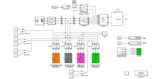
Power Harmonic Passive Filters | LMS Solution
Passive harmonic filters are series filters (which means that current goes through the filter) that are used to reduce or mitigate, harmonics to tolerable levels as defined by IEEE-519.Passive filters use the following items to ‘filter’ (or clean) the current wave: Input reactor Output reactor Shunt reactor Capacitor A passive filter consists of a series circuit of reactors and capacitors. Harmonic currents generated by, for example, a frequency converter are shunted by this circuit designed to have low impedance at a given frequency compared with the rest of the network. Among several harmonics solutions, a passive filter is a very common and effective mitigation method. Passive filters are designed to provide a low impedance shunt path for harmonic currents. In this way, the harmonic currents are deflected to the ground. Another function of passive filters is to suppress the flow of harmonic currents between parts of the system by tuning the passive elements to create resonance at a single frequency or a band of frequencies.Passive harmonic filters generally consist of capacitors, inductors, and resistors. An array of these elements is arranged in one or more shunt arms to form different topologies. Among popular topologies of passive filters are single tuned, second-order, third-order, and C-type filters.
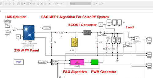
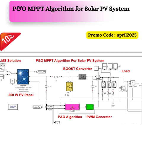
MATLAB -MPPT-PO-Solar PV System | LMS Solution Inter
MATLAB implementation of P&O MPPT for stand alone PV system.It is work with MATLAB 2017b version.
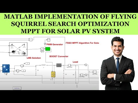
MATLAB Implementation of Flying Squirrel Search Optimization MPPT for Solar PV System
A call for a greener tech future that invites change and sparks debate.
#SustainableIT,
#GreenComputing,
#EnergyEfficiency,
#eWasteReduction,
#DigitalSustainability,
#GreenEnergy,
#TechForGood,
#DataCenterGreen,
#CleanTech,
#DigitalGreen,
#EcoTech,
#FutureTech,
#GreenInnovation,
#JoinGreenTech,
#ActNow,
#GlobalGreen,
#TechSuccess,
#GreenChallenges,
#TechOpportunities,
#BrightFuture,
#NextGenGreen,
#GreenSteps,
#EcoAction,
#InnovateGreen,
#CleanInnovation,
#GlobalUnity,
#GreenWorld,
#EcoEconomics,
#SmartBusiness,
#GreenPolicy,
#SustainableRules,
#GreenLearning,
#TechAwareness,
#CommunityTech,
#CollaborateGreen,
#MeasureGreen,
#SmartMetrics,
#NextGenGreen,
#YoungTech,
#EmbraceChange,
#FutureGreen,
#VisualGreen,
#ArtAndTech,
#BoldTech,
#GreenLegacyhttps://medium.com/@sanjay.mohindroo66/green-bytes-the-journey-towards-sustainable-it-green-computing-d43134869d5f
Green Bytes: The Journey Towards Sustainable IT & Green Computing.
This post explores sustainable IT practices, energy-efficient computing, e-waste reduction, and green digital infrastructures to spark dialogue and inspire action. In our fast-moving world…
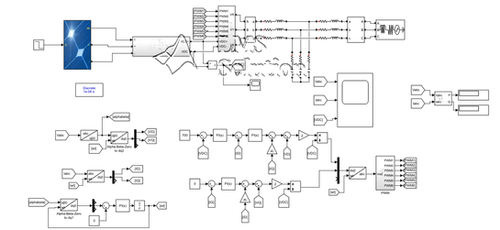
MATLAB - Grid Connected 100 kW Solar PV system | LMS Solution
A 100-kW PV array is connected to a 0.4 kV grid via a DC-DC boost converter and a three-phase three-level Voltage Source Converter (VSC). Maximum Power Point Tracking (MPPT) is implemented in the boost converter by means of a Simulink® model using the 'PO + Proportional Integral Regulator' technique. The detailed model contains the following components: PV array delivering a maximum of 100 kW at 1000 W/m^2 sun irradiance. 5-kHz DC-DC boost converter increasing voltage from PV natural voltage (290 V DC at maximum power) to 700 V DC. The switching duty cycle is optimized by an MPPT controller that uses the 'Incremental Conductance + Integral Regulator' technique. This MPPT system automatically varies the duty cycle in order to generate the required voltage to extract maximum power. 1980-Hz 3-level 3-phase VSC. The VSC converts the 700 V DC link voltage to 230 V AC and keeps the unity power factor. The VSC control system uses two control loops: an external control loop that regulates DC link voltage to +/- 250 V and an internal control loop that regulates Id and Iq grid currents (active and reactive current components). Id current reference is the output of the DC voltage external controller. Iq current reference is set to zero in order to maintain the unity power factor. Vd and Vq voltage outputs of the current controller are converted to three modulating signals Uabc_ref used by the PWM Generator. The control system uses a sample time of 100 microseconds for voltage and current controllers as well as for the PLL synchronization unit. Pulse generators of Boost and VSC converters use a fast sample time of 1 microsecond in order to get an appropriate resolution of PWM waveforms.
Many municipal governments are far more
#progressive than their provincial and federal counterparts. The recommendations they formulated would certainly increase the health and security of cities.
#infrastructure #energyefficiency #community #cdnpoli #election2025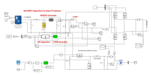
PV System With Battery Storage Using Bidirectional DC-DC Converter | LMS Solution
PV (Photovoltaic) systems are one of the most renowned renewable, green and clean sources of energy where power is generated from sunlight converting into electricity by the use of PV solar cells. Unlike fossil fuels, solar energy has great environmental advantages as they have no harmful emissions during power generation. In this work, a PV system with battery storage using a bidirectional DC-DC converter has been designed and simulated on MATLAB Simulink. The simulation outcomes verify the PV system‘s performance under standard testing conditions.


