girl who flirts with you by sending you drone parts (with firmware to extract and reverse-engineer)

everyone who follows the news knows the UA side is proudly using Ardupilot

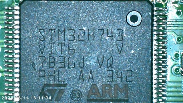
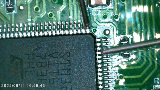
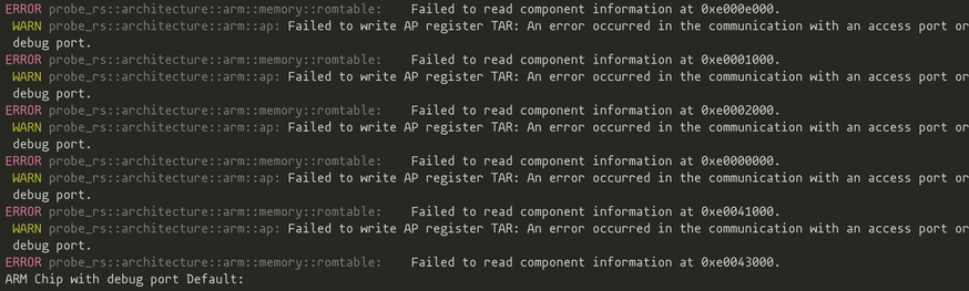
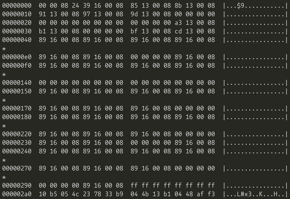
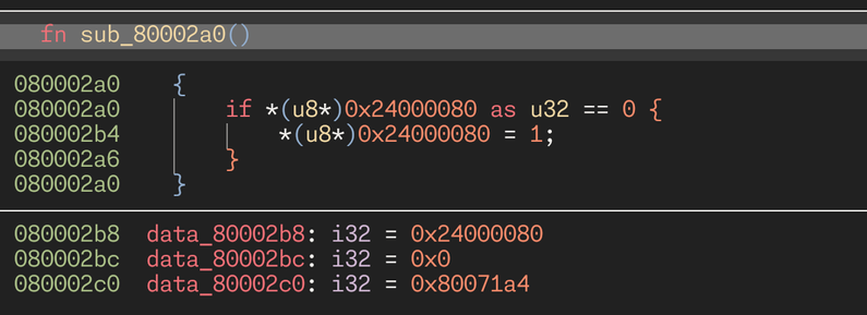
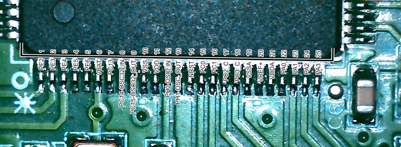
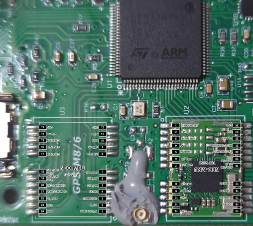
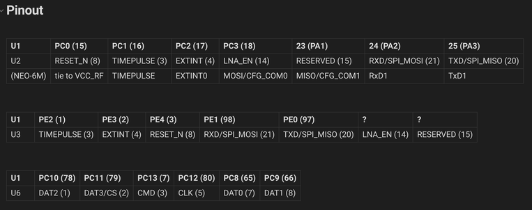
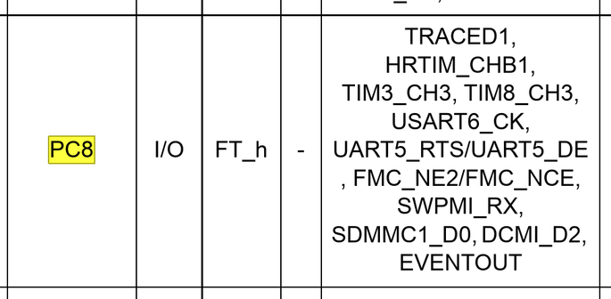
however nobody seems to know what the RU side is using. time to find out, i have an STM32 on my desk and a glasgow with newly added SWD support

weapons

i need these two pins for SWD

at the factory, they most likely used serial programming, which i don't want to use as i'm unfamiliar with it and it's not even easier (the board has an RS232 level shifter, etc)

ok, now i just need to power it

conveniently, there is silk that explains how to do that

it uses an LDO, so i don't think i actually need +24V, probably anything above 5V will work. i'll hook it up to a current limited supply first

as expected, we have trouble! it draws like 1.5 watts while the supply is sagging down to 3.6 V. those 1.5 watts are going somewhere, and it sure as heck isn't the STM32 or the ublox M8! time for some thermal imaging

the fusion is pretty bad at this distance, but it's probably this capacitor has broken down

it was an identical capacitor on the other side. and i had to find out with my finger, because it got hot but not hot enough to instantly evaporate IPA (i was conservative with current)

after spending 30 minutes fucking around with the grabber hooks (never use these. seriously. just solder a wire or something. you'll only short out your DUT with the hooks) i discovered that one of the connectors on the board actually just has SWD on it

? SWCLK GND SWDIO ?

also it seems to be a 1.8 V IO bank

nope i'm wrong, it just doesn't work properly on anything under 24 V (i'm not sure why i thought it would. bad assumptions)

and it's just a normal 3.3 V design

Here we go

ok, new problem

it responds over SWD... sometimes

i _think_ the board is attempting to boot and in the process of that browning out and resetting itself. maybe the u-blox has some dead capacitors, maybe something else; this is difficult to diagnose. all i know the power LED seems to go out briefly every second and the SWD interface doesn't work consistently

conveniently they put NRST on the same debug connector

so it's

RESET SWDIO GND SWCLK ?

okay, it doesn't seem to brown out any more, and probe-rs no longer crashes with an SWD error

however, because enough ROM tables are in reset, i can't get `probe-rs info` to work

for unclear reasons probe-rs continues to crash in some odd ways, so i think i have no choice but to grab ADIv5.2 and try to read the firmware myself? i have really not expected to have to do this...

the problem with this is that this is an uhhhhhh very special device

jebani dostawcy

at least the docs explain which of the three AXI MEM-APs belong to what
fortunately, glasgow lets you write scripts, so i wrote this quick script that lets me read memory while ignoring all errors by resetting the SWD interface whenever they happen

oops i was reading ITCM instead of Flash which is at 0x08000000

now _this_ looks like code (the very start of the firmware doesn't have anything interesting in it)

(holding "identifying firmware" book)

yep. that's firmware

based on strings in the firmware, it looks like it's using this exact STM32 bootloader

the bootloader repo is over 300 MB in size because they checked in a build of an Android app that you can use to reflash the thing

https://github.com/Embetronicx/STM32-Bootloader

GitHub - Embetronicx/STM32-Bootloader: STM32 Custom Bootloader from scratch

STM32 Custom Bootloader from scratch. Contribute to Embetronicx/STM32-Bootloader development by creating an account on GitHub.

GitHub

perfect match

(the \n was probably chomped off by clang as it turned printf into puts. yes, this is a valid optimization it does)

besides one or two functions in the bootloader, there are no strings in the firmware

the application section is a 128K blob full of vector floating point instructions. this is going to be extremely challenging to reverse engineer

okay i think i know why it was unstable

remember that broken down capacitor that i removed? it was on the VIN pin of a TPS5430 buck converter. and TPS5430 really, _really_ wanted its VIN pin to be bypassed

implemented memory dumping via SWD so that you don't have to rely on other tools that may or may not be able to identify the chip https://github.com/GlasgowEmbedded/glasgow/pull/898
Implement memory dumping via SWD probe by whitequark · Pull Request #898 · GlasgowEmbedded/glasgow

This avoids the need to use a debugger or identify the chip in any way, hence it works well for reverse-engineering.

GitHub

looking at this firmware: it has no strings (except in the bootloader), very little structure i can recognize, and is basically a 128K sized blob of numeric code

i don't think it's one of the popular open-source firmwares. definitely not as-is, and probably not even a modified one; i would expect vtables, command parsers, stuff like that; none of it is there

when reverse-engineering embedded devices, i like to make these overlays

to make one yourself, open the datasheet screenshot in gimp, use "select by color" on the _black_ (this is important), grow the border by 1-3 px, copy the selection, paste onto a photo, and use universal transform until it matches

here's another one

i had to expand the u-blox symbol a bit since they didn't quite get the spacing right

for some reason people expect military firmware to do things like "code protection", "encryption", or "obfuscation"

they forget this firmware is usually made in a rush, by the lowest bidder, and (quite likely) by someone who doesn't really care about the craft

i have never seen any RE countermeasures

the end result of connectivity extraction for me is usually these tables

i played myself, the firmware doesn't actually use the SDMMC1 peripheral except to enable its power :/

and i'm fairly sure it's not being used with the SPI peripheral either, given PC8 is connected to DAT0/MISO

i've never seen resistor markings like this

are these jumpers?

i'm going to make a bet that nobody has tried to reverse-engineer Thumb code with VFP instructions in Binary Ninja before

i opened one trivial function and immediately found three bugs, one of which is a show-stopper

https://github.com/Vector35/binaryninja-api/issues/6945
https://github.com/Vector35/binaryninja-api/issues/6946
https://github.com/Vector35/binaryninja-api/issues/6947

implemented a glasgow applet for sniffing conversations over UART with accurate sequencing; this will be used for finding out how the MCU talks to the GPS module

https://github.com/GlasgowEmbedded/glasgow/pull/899

Add an UART sniffer applet by whitequark · Pull Request #899 · GlasgowEmbedded/glasgow

On the command line this applet admits only two channels, rx and tx, but when UARTAnalyzerInterface is used directly, up to 64 channels may be used.

GitHub

just realized that i can't exactly expect this device to work as intended right now, because it doesn't have its IMU

and it needs an IMU, alongside GPS, to know where it is

using the new `uart-analyzer` applet i have obtained the exchange between the MCU and the GNSS module. it is a binary stream in a format unknown to me. for obvious reasons i will not be posting a screenshot of it

of _course_ this device pair is being annoying and switching UART speed at runtime

i didn't implement autobaud in uart-analyzer applet because i thought it 'would not be that important'. agh

adding proper autobaud is fairly tricky for the analyzer, but i did at least add per-channel baud (i.e. you can have different baud rates for RX and TX)

an online ublox protocol decoder (implemented e.g. as a script) could promptly switch baud rates when it observes a command to do so

i've reverse-engineered the entire state machine in the firmware. it only parses three messages! these are:

UBX-NAV-PVT
UBX-NAV-SOL
UBX-NAV-SAT

once again, the firmware is... simple. every part i can understand does exactly one thing, in the most uncomplicated way possible

i think this has a buffer overflow

yeah, it reads data from the GNSS module into a preallocated buffer that has space for about 32 satellites (i'm not clear on how many exactly but definitely not more than that)

the GNSS module has 72 channels

... i think this is technically a 0day?..
@whitequark what would be the correct way to responsibly disclose this (to the SBU)

@rcombs beats me

but i also would expect the SBU to know basic shit like this already. to the best of my knowledge the devices i have are of little operational interest, Ukrainian electronic warfare is far ahead of what these devices can tolerate

@rcombs @whitequark This is a good example of why I don't like the term "responsible disclosure".
@whitequark *giggle*

@whitequark

UBX-NAV-PVT length = 92 bytes
UBX-NAV-SOL length = 52 bytes
UBX-NAV-SAT length = how many satellites can you see right now?

@jpm @whitequark I wonder what happens if you give the GPS receiver signals from too many satellites (well, pretend satellites ideally). There is likely some limit (possibly implemented safely) in the GPS firmware but it may still be higher than the length of this buffer...

@chrisgj198 @jpm it overflows the buffer

i don't know how long it is exactly because it appears to never check the buffer but it's like half the module channel count

@whitequark clearly they should’ve written it in rust /s
@whitequark wait what it's dynamically changing the uart speed? Between what bauds?
@azonenberg 9600->115200

@whitequark @azonenberg yep u-blox receivers can do this, there’s a command sequence from the host to the receiver that does it.

And in the intended application, it makes sense to do so because I’ll bet one of the next commands is to increase the frequency of navigation messages up from the default of 1Hz

@jpm @whitequark Yeah it makes sense to run fast, booting at 9600 doesn't.

can you not just nonvolatile-ly configure the ublox to boot up at 115200 out of the box?

@azonenberg @jpm @whitequark you can, but that still has to be done at some point, and you don't want to make assumptions about what changes with different firmware versions, or if the receiver dumps the configuration (I've seen all of the above catch people out)
@azonenberg @whitequark booting at 9600 does make sense because factory config spits out NMEA at 1Hz. It also depends on exactly which receiver in the range it is, only some have actual non-volatile flash for storing configuration, the rest are only non-volatile as long as battery backup power is applied…
@whitequark particularly common for figuring out where a ublox device is. (ArduPilot does the same thing)
@whitequark the missile doesn't know where it is because it doesn't know where it wasn't?
@azonenberg it's not a missile! it's a loitering munition

@azonenberg actually i'm not sure what this specific device should be called because it shouldn't have carried a warhead, it's a decoy

is that still a munition? i guess it is

@whitequark military-grade software (derogatory)

@natanbc military-grade anything (derogatory)

i always find it laughable when people use "military-grade" in marketing. like, you mean, "overpriced by a factor of 20, ten years out of date, built in a factory chosen by what's benefitting some politician, and used in imperial conquest? which of these things are desirable, exactly?"

@whitequark @natanbc
military grade lanyard for public meetings!
in camo colors ofc
@whitequark @natanbc My grandpa who was in the military gave me a can opener at one point and said "you know what this is? The only thing the army ever issued to us that worked worth a shit."
@whitequark fascinating thread, interested to see where it goes!
@whitequark that's a really good tip, thank you.
@whitequark do you think it has been manually coded (C code?) and runs bare metal? Seeing the bootloader approach let's me guess that they may also have used STM32 HAL/LL code. Or aren't there any other peripherals than the GPS/navigation module? Generated code for math stuff?

@maehw it just uses a few USARTs (i think 1, 2, and 6 at least, but i haven't fully traced the board yet) and an SDMMC peripheral. and GPIOA bank. nothing else as far as i can tell, very conservatively written

probably C, and definitely no major OS (Linux runs on this chip apparently?)

if there's an RTOS i haven't seen traces of it, but i might've missed it

@maehw on a second thought, they are definitely using a HAL, the way resets are controlled for a peripheral has all hallmarks (ha!) of it
@whitequark TPS5430 can have a little rail collapse,,, as a treat
@gsuberland it caused so much EMI that the glasgow would frequently re-enumerate, which was incredibly spooky
@whitequark
Interesting, never had that. What would you suggest to prevent that? Some mini faraday cage for the glasgow? Earthing the (metal) shell of the Glasgow?
@gsuberland
@magnetic_tape @gsuberland to place the USB connector side away from the DUT would be the cheapest :)
@magnetic_tape @whitequark it's probably conducted EMI and fairly hefty ground bounce due to the missing cap, nothing you can do really except put the bypass cap back into the device that's supposed to have it.