what if I made a little visual programming language for my synthesizer 🤔
I'm considering replacing the register machine I wrote with an evaluator graph as a convenience for polyphony, but this would also open up the possibility of live editing patches. My register machine allows for no flow control, and each operation has at most two inputs and exactly one output. This is geometrically very convenient, so I'm thinking maybe something grid based to hopefully keep it simple.
Another thing that would be nice is being able to make patch-specific touch interfaces.
I'm thinking something like this for the visual language frontend. The nodes are grid aligned with space between for connections to run. Placing a new node in that space would insert a new row or column into the grid. Wire paths will probably be automatic, and the whole thing would ideally have a deterministic textual representation to make revision control easier.
Also important: graph cycles are allowed. If there's a feedback loop, the value is pulled from the previous frame's computation or is zero if there is no previous frame.
Commutative instructions get to be variadic. I'm not sure what to do about non-commutative instructions syntaxwise. I'll probably have it make you select which parameter your connecting when you draw a connection, and then display information about the connection when you touch wires, and draw the name along the wire where possible. Color coding and ordering where the inputs connect also would make sense to supplement that.
I'm really tempted to just not have division or subtraction, and provide rcp and sign flip as instructions instead. Likewise who needs clamp when you've got min(max(v, low_bound), high_bound), right? I think I'd want lerp and some other functions that don't really fit this syntax well though so idk I'll have to think about that.
One of the fun things about designing a visual programming language is "how can I put less work making this" and "what if it wasn't super annoying" can coincide on the same solutions! Like what if instead of trying to drag and drop a noodle between two nodes on opposite sides of the world, what if you just select both and enter noodle mode that temporarily puts them side by side so you can draw the connections you want.
also graph travel mode. zoom in on one thing and just see what's connected to it and travel to neighbors
i have no share holders! no KPIs! no customers! the ux only has to be awesome for meeeee! bweeehehehe!
playing around with the rules for automatic wire placement tonight and i got a marvelous idea. normally i'd want to avoid parallel runs of wires when it improves readability to do so, but the exception to this rule is if the destination is the same then its better to consolidate. here's a mock up
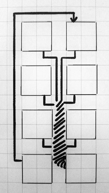
my current wire placement rule set is this:
1. groups of wires that all connect to the same parameter on one node are evaluated to see if a wire wrap path makes sense. if so, these are placed first, and the cost of the path is raised arbitrarily high for other wires.
2. wires that travel the farthest go second and search for the shortest path with the fewest bends
3. wires that have the shortest path go last, avoid parallel runs, but favor perpendicular crossings
ideally things will be color coded by destination and wires will have different colors and textures to make it easier to tell them apart, as well as UV animation. Also highlighting / isolating connections when you select things.
another thing I want is a mode for isolating parts of the patch. stuff like selecting a node and having it highlight it's connections is common place, but I'd also like to have a mode for isolating the entire expression tree that roots on that node. dunno if anything does that.
I figure the eagle eye view of a patch can be a little obtuse if I have reasonable tools for examining, navigating, and organizing what I have.
also I am delighted that people keep thinking of examples of games instead of other visual programming languages in response to this thread. it's one of the ways I know I'm on the golden path.
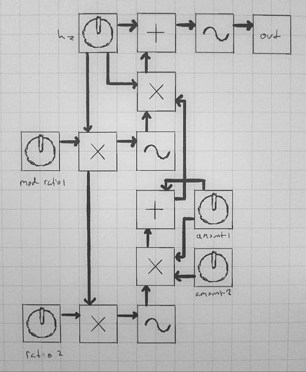
I put it to the test by translating my test patch from my python fronted to a hypothetical equivalent node based representation without regard for wire placement and then stepped through my wire placement rules by hand. I'm very pleased with the results, it's a lot clearer to me what it does than the python version is at a glance.
I want this to be real so bad XD
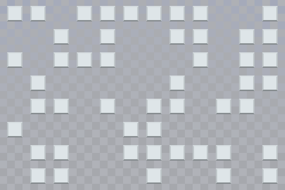
Test grid background and placeholder tiles. I wasn't quite aiming for windows 9x buttons but it sorta veered that way. dunno if I'll keep them
now, this may seem like I'm just fussing around on trivial details, but i assure you this is all going according to plan
@aeva as a placeholder it's fine, keep going
@aeva ME TOO. I already wanna hack on it.
@aeva embrace the homies and make it real! 
it looks really cool, I love visual programming languages and I never thought about making a grid-based one :3
@aeva this is one of those threads that has me saying to myself "how is Aeva so smart and correct" and I'm not sarcastic or kidding
@aeva you probably should not imitate the Rocky's Boots / Robot Odyssey UI, but you are for sure bringing it to mind
@aeva factorio does this thing with multi line colors so you can have multiple parallel lines on the same cell but going to different places
@pupxel yeah I'm gonna have something like that too, but I really love the visual emphasis the wire wrap has. like imagine that's six oscillators funneling into a sum at the bottom right. it looks different than everything else in the patch that isn't six oscillators funneling into a sum.
@aeva clever merging in that scenario is something that would be really useful, but doesn't exist in almost any software. Even things used specifically for diagramming like draw.io don't understand the concept. I want to see this basically everywhere...
@viraptor seriously! personally I think the designers of those programs could stand to go off the deep end with procgen stuff. they should stop trying to copy the same stale ideas from eachother and start trying to copy townscaper and that other one that came out recently
@aeva oh but you do! future you is a share holder!
@aeva living the dream
@aeva making your own music software rules so hard

@aeva honestly the best UIs out there were made that way..
@snowyfox I don't get it
@aeva This is true freedom.
@aeva don't forget grouping! like creating a virtual node containing multiple stuff
@aeva fuuuuuuuck I love that idea, why… why is this not normally a thing for these kinds of graph visualisations 😭
@aeva
That's really using your noodle!
That's really using your noodle!
@aeva you can do clamp as median which is commutative
@aeva clamp(x, lo, hi) = med3(x, lo, hi) if lo <= hi
proof:
suppose x < lo. then x < lo <= hi so lo is the median.
suppose lo <= x <= hi. then x is the median.
finally, suppose hi < x. then lo <= hi < x so hi is the median.
@steve @aeva Yup. And you can also use this in reverse for median nodes if you have them.
Specifically, for med3(a,b,c), during "code gen", swap all constant inputs to the right as necessary, and in nondescending order (via commutativity).
Then if b is constant, so is c, b <= c, and
med3(a,b,c) = max(min(a, c), b)
-> med3 is actually a pretty convenient IR for this. Symmetries are good!
@rygorous that's awesome
@aeva Reciprocal and negation/inverse would let me cover basic arithmetic in combination with an attenuverter that can scale and offset a signal. Perfectly chromulent way of subtracting/dividing.
Clamp in a single node can be useful, but through minimalism goggles, I'd see that as a special case of wave-shaping.
(Spent a minute building this in Bespoke Synth, but then realised it's quicker in Ableton. Bespoke's waveshaper lets you input maths expressions, so would kinda miss the point anyway.)
@nex someone pointed out in another reply branch that clamp can be expressed as a median of 3 values, which is commutative, so that would be a good candidate for a single instruction
@aeva Whoa … from the point of view of an idiot who wants to munge signals that traverse noodles, that's not the most intuitive way of doing clamp. BUT:
From a nerdy point of view, it's really intriguing how this node would generalise to accept any number of inputs. When you consider how median is defined for an even number of inputs, this could also provide an average of two values, and probably be abused in even more delectable ways ^_^
@nex median wouldn't be the average, but also idk what the most useful interpretation of clamp would be for more than three values. I figure I'd just have it only accept three values.

@aeva Adobe had a concept I really liked here which is a “poisoned” bit on values, so you can eg have out of range values still propagate through UI but have the downstream stuff turn red or w/e to indicate the problem
@Catfish_Man I'm thinking of simply making it impossible to express broken patches through the syntax.