Inspired by the news that HiFiBerry are releasing an 8-channel DAC board for the Raspberry Pi 5, but slightly disappointed they’ve sold out of their beta-test programme, coupled with the news that Rene has added 4-channel I2S support for circle, and seeing that the HiFiBerry dac8x is essentially four PCM5102A modules and a high quality audio path, I set out attempting to create a similar (albeit low quality) equivalent with four GY-PCM5102 modules.

Warning! I strongly recommend using old or second hand equipment for your experiments.  I am not responsible for any damage to expensive instruments!

If you are new to single board computers, see the Getting Started pages.

Parts list

  • Raspberry Pi 5.
  • uSD card, HDMI, mouse, keyboard, etc to boot Raspberry Pi OS.
  • 4x GY-PCM5102A modules.
  • Breadboard and jumper wires.

The Circuit

The Raspberry Pi GPIO Pins are connected as follows:

Raspberry Pi 5GY-PCM5102A Modules5VVCC – Modules 1-4GNDGND and SCK – Modules 1-4GPIO 18BCK – Modules 1-4GPIO 19LCK – Modules 1-4GPIO 21DIN – Module 1GPIO 23DIN – Module 2GPIO 25DIN – Module 3GPIO 27DIN – Module 4

I eventually ended up using a small solderless breadboard to allow me to daisy-chain the power and common signals for the GY-PCM5102 modules.

Important: Recall that for these PCM5102 modules, there are solder jumpers that have to be setup on the back. More details here.

Raspberry Pi OS

Before connecting any of the GY-PCM5102A modules, I downloaded the latest 64-bit Raspberry Pi OS image and booted it up “as is” on my Pi 5 to make sure everything was working.

Then I installed any pending updates and rebooting to ensure everything was once again up and running.

It might be worth checking sound is working by firing up an Internet browser and watching a video or something. By default the sound will go over HDMI, so naturally you need a sound-capable HDMI device to support that.

At this point I shut it down again and connected up the four PCM5102 modules as per the diagram above then booted everything up again. The OS should boot correctly although at this point it will have no knowledge of the added boards.

Quad DAC Configuration

The basic principle is to use a device-tree overlay file to enable I2S audio and the four PCM5102 devices.

But the nice people at HiFiBerry have already done this with support from Raspberry Pi for their dac8x module, so actually all that is required is to edit the file /boot/firmware/config.txt and add the following line:

/boot/firmware/config.txt:

dtoverlay=hifiberry-dac8x

There is talk on the Internet about commenting out the audio=on parameter or enabling i2s=on, but I didn’t have to do either of these.

Then on reboot, there should be a new audio device “snd_rpi_hifiberry_dac8x” which can be selected.

At this point playing a video should output on the first PCM5102 device.

To test all 8 channels requires an application that can output audio on 8 channels. But for a simple test the “speaker-test” command can be used from the terminal:

kevin@pi5:~ $ aplay -l
**** List of PLAYBACK Hardware Devices ****
card 0: vc4hdmi0 [vc4-hdmi-0], device 0: MAI PCM i2s-hifi-0 [MAI PCM i2s-hifi-0]
Subdevices: 1/1
Subdevice #0: subdevice #0
card 1: vc4hdmi1 [vc4-hdmi-1], device 0: MAI PCM i2s-hifi-0 [MAI PCM i2s-hifi-0]
Subdevices: 1/1
Subdevice #0: subdevice #0
card 2: sndrpihifiberry [snd_rpi_hifiberry_dac8x], device 0: HifiBerry DAC8x HiFi pcm5102a-hifi-0 [HifiBerry DAC8x HiFi pcm5102a-hifi-0]
Subdevices: 1/1
Subdevice #0: subdevice #0

kevin@pi5:~ $ speaker-test -t sine -f 440 -c 8 -D hw:2

speaker-test 1.2.8

Playback device is hw:2
Stream parameters are 48000Hz, S16_LE, 8 channels
Sine wave rate is 440.0000Hz
Rate set to 48000Hz (requested 48000Hz)
Buffer size range from 16 to 32768
Period size range from 8 to 256
Using max buffer size 32768
Periods = 4
was set period_size = 256
was set buffer_size = 32768
0 - Front Left
4 - Center
1 - Front Right
7 - Side Right
3 - Rear Right
2 - Rear Left
6 - Side Left
5 - LFE
Time per period = 23.295314
0 - Front Left
^C 4 - Center
1 - Front Right
7 - Side Right
3 - Rear Right
2 - Rear Left
6 - Side Left
5 - LFE
Time per period = 0.406018
kevin@pi5:~ $

The “aplay -l” command can be used to list all devices that ALSA knows about. In my case the pseudo hifiberry dac8x device is listed as “card 2”. This means I then need to use the device identifier “hw:2” for the speaker-test command.

The other parameters to speaker-test are as follows:

  • -t sine – output a sine wave rather than the default noise output.
  • -f 440 – set the sine wave frequency to 440Hz
  • -c 8 – use 8-channel sound output.
  • -D hw:2 – use the device “hw:2”

If all goes well, then playback on 0,1 (front left/front right) goes to PCM5102 module 1; 2,3 (rear left, rear right) goes to PCM5102 module 2; and so on.

Closing Thoughts

Now that I know the basic principles seem to work, I want to see what it would take to create a 8-channel audio output MiniDexed.

Kevin

https://diyelectromusic.wordpress.com/2024/05/27/rpi-5-quad-stereo-sound-with-pcm5102a/

#0 #i2s #pcm5102 #raspberryPi #raspberryPi5

RPi 5 quad-lane I2S · rsta2 circle · Discussion #453

Apparently the RPi 5 supports 4 lanes of I2S output. Would it be possible to expand the I2S support from 2 channels to 8? The hifiberry-dac8x-overlay.dts appears to show how this could work for a q...

GitHub

Ok, ignore my last comment about Part 4 being my last post on this topic. I thought I ought to pull together all the hardware notes on how to build one as I haven’t really written that down anywhere.

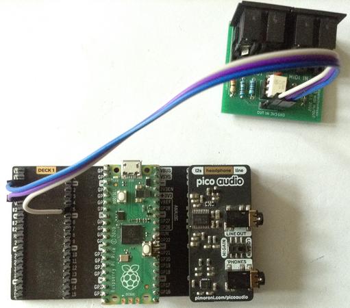
So this shows the connections required between the Pico, I2S DAC and MIDI IN.

  • Part 1 where I work out how to build Synth_Dexed using the Pico SDK and get some sounds coming out.
  • Part 2 where I take a detailed look at the performance with a diversion into the workings of the pico_audio library and floating point maths on the pico, on the way.
  • Part 3 where I managed to get up to 16-note polyphony, by overclocking, and some basic serial MIDI support.
  • Part 4 for the full MIDI implementation, voice loading, SysEx control and USB-MIDI.
  • Part 6 includes details of how to use PWM output.

The latest code can be found on GitHub here: https://github.com/diyelectromusic/picodexed

Warning! I strongly recommend using old or second hand equipment for your experiments.  I am not responsible for any damage to expensive instruments!

If you are new to microcontrollers, see the Getting Started pages.

The Circuit

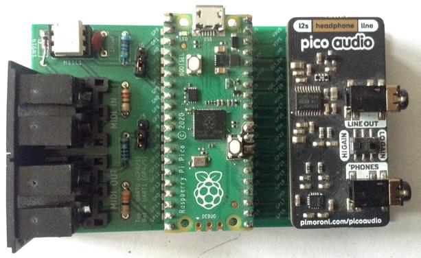
The easiest way to get a PicoDexed up and running for me, is to use one of my MIDI Proto PCBs and the Pimoroni I2S Audio Pack. This does not allow for any debug output.

Note the jumpers are set to use UART 1 on GP4 and GP5.

If only USB-MIDI is required, then the Audio Pack can be plugged directly onto the back of the Pico, in which case simply plugging into the Pico via USB to a computer and connected up the audio out will work.

It is also possible to use any 3V3 compatible MIDI module. The following shows the use of a Pimoroni “dual expander” with a MIDI module connected to GND, 3V3_OUT and GP5 (RX1).

This has the advantage that all other GPIO pins are available, so it is relatively straight forward to include a debug link via GP0/GP1 for UART 0.

A Solderless Breadboard Circuit

Of course it is also possible to build everything on a solderless breadboard.

The diagram below shows how a cheap GY-PCM5102 module can be used as the I2S DAC and a serial MIDI interface (optional) can be built using my standard 3V3 MIDI IN circuit.

This also allows for some debug output using UART 0 (GP0/GP1).

Things to note:

  • The PCM5102 board will have to have solder jumpers on the rear set as follows: 1=L, 2=L, 3=H, 4=L. Sometimes these come preconfigured with solder bridges, sometimes with zero-ohm SMT resistors, and sometimes with no connection made at all. More details here.
  • I always get pins 4 and 5 mixed up on MIDI DIN sockets. Here is my MIDI Connections Cheat Sheet which may help.

Pico GPIO Usage

The following GPIO pins are in use or allocated:

GP0Debug UART TX (unused at present)GP1Debug UART RXGP4MIDI TX (unused at present)GP5MIDI RXGP9I2S Data (DATA, DIN)GP10I2S Bit Clock (BCK)GP11I2S “Left/Right” Clock (LCK, LRCK, LR_CLOCK)GP20Optional: PWM outputGP22Optional: Mute pin for the Pimoroni Audio Pack (not used)VSYS5V power to DAC (if required)3V3_OUT3V3 power to MIDI IN (if required)GND

PWM Audio Output

It is possible to use PWM audio output on the Pico. Full details can be found here: Raspberry Pi Pico Synth_Dexed? – Part 6.

But this is a lot more limited than I2S and the quality is a lot poorer too. As a DAC can be obtained quite cheaply, the use of an I2S DAC is strongly recommended.

Closing Thoughts

I’ve uploaded a prototype UF2 file to GitHub in case anyone wants to give it a go: everything can be found here: https://github.com/diyelectromusic/picodexed

Hopefully there is enough information in the above to get something up and running.

Kevin

https://diyelectromusic.wordpress.com/2024/02/18/raspberry-pi-pico-synth_dexed-part-5/

#dx7 #midi #pcm5102 #picodexed #raspberryPiPico #usbMidi

Raspberry Pi Pico Synth_Dexed? – Part 4

I was going to leave things at Part 3 blog-wise, and just get on with filling in the gaps in code now, but I’ve come back to add a few more notes. But this is likely to be the final part now.…

Simple DIY Electronic Music Projects

Here are the build notes for my RPi 400 MIDI and Audio PCB.

Warning! I strongly recommend using old or second hand equipment for your experiments.  I am not responsible for any damage to expensive instruments!

In this case – inserting this pcb incorrectly (which unfortunately is possible with the RPi-400) could damage the RPi 400. See full post below for details.

If you are new to microcontrollers and single board computers, see the Getting Started pages.

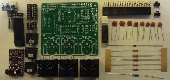
Bill of Materials

For the MIDI circuit

  • 1x H11L1.
  • 1x 74HCT14 (NB: Must be the HCT version, not the HC).
  • 1x 1N914 or 1N4148 signal diode.
  • 5x 220Ω resistors.
  • 1x 470Ω resistor.
  • 2x 100nF ceramic capacitors.
  • Either: 3x 5-pin, 180 degree PCB-mount DIN sockets (see photos for footprint).
  • Or: 3x stereo TRS PCB-mount sockets (see photos for footprint).
  • Optional: 6-way DIP socket; 14-way DIP socket.
  • 1x 2×20-way right-angle GPIO header socket.

For the additional DAC and MiniDexed sections:

  • 1x GY-PCM5102 DAC module.
  • 1x SSD1306 32×128 OLED display (pin order: GND-VCC-SCL-SDA).
  • 5x 10nF ceramic capacitors.
  • 2x 100nF ceramic capacitors.
  • 1x switched rotary encoder (see photos for footprint).
  • 2x slim toggle pcb-mount button switches (see photos for footprint).
  • Optional: 4-way header socket for SSD1306 display.

For structural support when installed:

  • 2x 2.5mm, 6mm nylon spacers
  • 2x 2.5mm nylon nuts

Build Steps

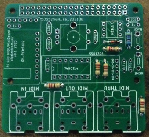
Taking a typical “low to high” soldering approach, this is the suggested order of assembly:

  • All resistors and diode.
  • DIP sockets (if used) and TRS sockets (if used).
  • Disc capacitors.
  • GY-PCM5102 module (if used) – check that the solder jumpers on the back (see below).
  • Buttons (if used).
  • 4-way SSD1306 header socket (if used).
  • GPIO headers.
  • DIN sockets.
  • Rotary encoder.

As mentioned in the design notes, it is possible to install the three main sections of the PCB independently depending on what is required:

  • The MIDI circuits.
  • The PCM5102 DAC.
  • The MiniDexed IO components (display, encoder, buttons).

If a DIP socket is used for the 74HCT14 the to install the SSD1306 display will probably require a 4-way header socket in order to lift it high enough to avoid the installed 74HCT14 and to not negate any benefits of having the chip in a socket!

If the H11L1 and 74HCT14 are soldered directly to the board then a SSD1306 with extended pin headers should be adjustable enough to be soldered over the other components.

The capacitors that are labelled “10p” are actually 10nF capacitors. This is an error in the silkscreen.

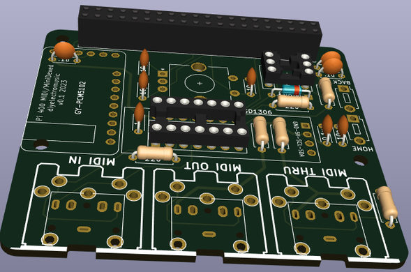
Here are some build photos for a complete build with all sections complete.

At this point the MIDI sections are complete and it is possible to now install the TRS or DIN sockets and the GPIO header if a MIDI only board is required.

To continue building the DAC and IO sections see below.

Note check the PCM5102 jumper settings before fixing – more here. Also note how the capacitor for the PCM5102 is folded down underneath the board.

At this point the TRS or MIDI sockets can be installed.

Once complete, it is strongly advised to add a couple of 2.5M 6mm spacers to the middle of the PCB in order to support it when plugged into the RPi 400. This is particularly important if using a switched rotary encoder and the buttons.

As one of the holes for the spacers is under the corner of the PCM5102, it might need trimming down slightly to fit without pushing the PCM5102 upwards. In my case I had to cut the thread down slightly as shown in the photos below.

Here is the final board.

Testing

I recommend performing the general tests described here: PCBs.

Once the above tests were complete, I tried the board with a Raspberry Pi 3A+ on the basis that if something went wrong it would cost me a lot less to replace a 3A+ than my new RPi 400.

Care must be taken to orient the board correctly though when not using a RPi 400 – see photos below.

Once all seems to be functioning, I switched to my Raspberry Pi 400.

IMPORTANT: Additional care must also be taken when installing in a RPi 400 as it is quite possible to plug the board in “one pin out”. If this happens, then there is a distinct risk of connecting one of the 5V GPIO pins to GND which would damage the RPi 400.

With hindsight, the use of a keyed header socket (assuming they exist in right-angled, pcb-mounted format) would stop this happening.

If I rebuild this board, then I might leave pin 4 5V unconnected to prevent this happening. I don’t think any other power pins are adjacent to GND, although it still leaves the possibility of feeding a HIGH GPIO directly to GND in other places.

PCB Errata

There are the following issues with this PCB:

  • As mentioned before, the capacitors labelled “10p” are really “10n”.
  • The pcb slightly overlaps the uSD card slot on the RPi-400 which means it can’t be removed when the pcb is installed.
  • Inserting incorrectly could connect GPIO 5V to GND and damage the RPi 400.

Find it on GitHub here.

Sample Applications

MiniDexed Raspberry Pi 400

The board is essentially a mirror of my MiniDexed Raspberry Pi IO Board physically arranged to support the Raspberry Pi 400 form-factor.

Below are the key minidexed.ini configuration settings that allows the RPi 400 to act as a MiniDexed synth with this board.

The MIDIThru setting is not required for general operation but can be used to turn on software MIDI THRU between the IN and OUT ports.

Also, MIDIThru can be used to direct the RPi 400 keyboard to the MIDI OUT port, turning it into a MIDI controller. The internal keyboard is device “ukbd1” which needs linking to “ttyS1” for the MIDI interface.

SoundDevice=i2s
#MIDIThru=ttyS1,ttyS1
MIDIThru=ukbd1,ttyS1

LCDEnabled=1
SSD1306LCDI2CAddress=0x3C
SSD1306LCDWidth=128
SSD1306LCDHeight=32
SSD1306LCDRotate=0
SSD1306LCDMirror=0

LCDColumns=20
LCDRows=2

ButtonPinPrev=0
ButtonActionPrev=
ButtonPinNext=0
ButtonActionNext=
ButtonPinBack=5
ButtonActionBack=click
ButtonPinSelect=11
ButtonActionSelect=click
ButtonPinHome=6
ButtonActionHome=click
ButtonPinShortcut=11

EncoderEnabled=1
EncoderPinClock=10
EncoderPinData=9

The built-in keyboard can be used as a simple 2-octave music keyboard to play the synth as follows:

Raspberry Pi 400 MIDI and Audio Interface

The board can be used as a MIDI and audio interface for the standard Raspberry Pi 400 OS too.

The basic idea is to use a I2S DAC overlay for the PCM5102 and to enable the serial port, but not the serial console, in the raspi-config and map MIDI onto it in some capacity.

Enabling the PCM5102 Sound

The full instructions are the same as described here: https://learn.pimoroni.com/article/raspberry-pi-phat-dac-install
But the short version (for 32-bit Raspberry Pi OS “bullseye”) is as follows.

Edit /etc/config.txt and comment out or add the following:

# dtparam=audio=on
dtoverlay=hifiberry-dac

There are other settings in there related to I2S but these can be ignored as the overlay file will include everything it needs. Note: commenting out the audio=on line will disable the built-in audio via the bcm device in the Raspberry Pi.

Then create an /etc/asound.conf file with the following:

pcm.!default {
type hw card 0
}
ctl.!default {
type hw card 0
}

According to this document, this tells ALSA (the Linux sound system) to override its own default with hardware card 0, which is now the PCM5102. This can be confirmed using the command:

pi@raspberrypi:~ $ cat /proc/asound/cards
0 [sndrpihifiberry]: RPi-simple - snd_rpi_hifiberry_dac
snd_rpi_hifiberry_dac
1 [vc4hdmi0 ]: vc4-hdmi - vc4-hdmi-0
vc4-hdmi-0
2 [vc4hdmi1 ]: vc4-hdmi - vc4-hdmi-1
vc4-hdmi-1
pi@raspberrypi:~ $

For it to work though I have to then select the “snd_rpi_hifiberry_dac” option in the “Device Profiles” by right-clicking on the Raspberry Pi OS Desktop “sound” icon in the tray (next to the clock).

Enabling Serial (UART) MIDI

Serial MIDI is linked up to the Raspberry Pi’s GPIO TX/RX ports on pins 14 and 15. But by default there are a couple of issues with just hooking these up to a MIDI interface:

  • They are usually either expected to be used with a serial console or configured (apparently) for a faster Bluetooth link.
  • The supported baud rates don’t include the standard MIDI 31250 baud.
  • By default there is nothing that will connect a UART based serial port to ALSA to allow it to be used.

Details of how to solve this can sort of be found around the Internet, but I’ve not found a complete “just do this and everything works, and this is why” document. The official Raspberry Pi documentation for the UART can be found here: https://www.raspberrypi.com/documentation/computers/configuration.html#configuring-uarts (although to be honest, I didn’t quite follow most of it myself… primary UARTs? Hmm)

Other references:

First enable the serial port and disable the console. This can be done by editing /boot/config.txt directly, but can also be done from the Raspberry Pi Configuration GUI tool.

Then in /boot/config.txt these additional updates are required:

enable_uart=1
dtoverlay=miniuart-bt
dtoverlay=midi-uart0

The first is probably already there if the serial port was enabled using the GUI. The second one apparently switches the internal Bluetooth over from using TX/RX on pins 14/15 to using ttyS0 (it is also possible to disable it completely with “disable-bt”). This frees up ttyAMA0 (TX/RX) for our use, which is the first UART on the PL011 peripheral on the bcm chip. The last setting includes some magic to tweak the clocks and baud rates so that the standard rate of 38400 will actually come out at the MIDI rate of 31250.

Details of each of these overlays can be found in the Raspberry Pi documentation (the README) here: https://github.com/raspberrypi/firmware/tree/master/boot/overlays and details of how the UARTS are set up and used on the different Pi versions, and which options are available, can be found here: https://www.raspberrypi.com/documentation/computers/configuration.html#configuring-uarts

Note: there are variants of midi-uart for other UARTs (which apparently can be enabled on a RPi 4) and a special midi-uart0-pi5 version for the Raspberry Pi 5.

This should have enabled the primary UART on TX/RX (pins 14,15) to be available with a suitable MIDI baud rate. But to use it, that serial port needs linking up to the operating systems sound setup.

Apparently the most common way to do this appears to be to use the ttymidi tool, which I guess fulfils a similar function to hairless-midi on a Windows PC (although I note hairless says it supports Linux too, even though it too recommends ttymidi!).

Unfortunately there doesn’t seem to be a ready-made version just to install, so it has to be built. The instructions from here worked fine for me:

$ sudo apt-get install libasound2-dev
$ wget http://www.varal.org/ttymidi/ttymidi.tar.gz
$ tar -zxvf ttymidi.tar.gz
$ cd ttymidi/
$ make
$ sudo make install

Once installed this needs to be started to connect the serial port to ALSA:

$ ttymidi -s /dev/ttyAMA0 -b 38400 -v

This provides the serial port and baud rate (remember 38400 has been tweaked to really be 31250 “on the wire”). The “v” option means it will dump any messages to the console. An optional “n” option can be used to give the link a nice name that can be used later. Without it, it defaults to “ttymidi”.

Two additional, useful tools to install (using the Raspberry Pi Add/Remove Software tool) are pmidi and midisnoop. pmidi can be used to list MIDI devices.

pi@raspberrypi:~ $ pmidi -l
Port Client name Port name
14:0 Midi Through Midi Through Port-0
128:1 ttymidi MIDI in
pi@raspberrypi:~ $

The ALSA tool aconnect can also list available ports:

pi@raspberrypi:~ $ aconnect -l
client 0: 'System' [type=kernel]
0 'Timer '
1 'Announce '
client 14: 'Midi Through' [type=kernel]
0 'Midi Through Port-0'
client 128: 'ttymidi' [type=user,pid=2619]
0 'MIDI out '
1 'MIDI in '
pi@raspberrypi:~ $

MIDIsnoop can be configured to use these ALSA ports and then can be used to show everything working.

How to actually use the ports I’ll might come back to, but in essence that becomes a tutorial in how to use ALSA and sound on Linux and there are lots of tutorials about that out there already.

At some point I’d like the above to all happen automatically on startup so that ttymidi is running and available to ALSA. That should be possible to add to one of the startup scripts, but that is left as an exercise for the reader (i.e. I haven’t looked that up yet).

Closing Thoughts

The “off by one” possibility of error when plugging the board in is concerning. I’d not anticipated that! But by being careful that should be manageable.

I also wasn’t anticipating not being able to unplug the uSD card! Oh well.

Apart from that, I’m really pleased with how it works.

At some point I might return to this and detail how to drive the display from Raspberry Pi OS itself as that would be a nice way to finish things off.

Kevin

https://diyelectromusic.wordpress.com/2023/12/18/rpi-400-midi-and-audio-pcb-build-guide/

#midi #MIDIThru #minidexed #pcb #pcm5102 #raspberryPi400
RPi 400 MIDI and Audio PCB Design

Now I’ve got my Raspberry Pi 400 up and running I’ve built a MIDI and I2S audio add-on board for use with the GPIO. Build guide here: RPi 400 MIDI and Audio PCB Build Guide. Warning! I …

Simple DIY Electronic Music Projects

Now I’ve got my Raspberry Pi 400 up and running I’ve built a MIDI and I2S audio add-on board for use with the GPIO.

Warning! I strongly recommend using old or second hand equipment for your experiments.  I am not responsible for any damage to expensive instruments!

If you are new to microcontrollers and singled board computers, see the Getting Started pages.

The Circuit

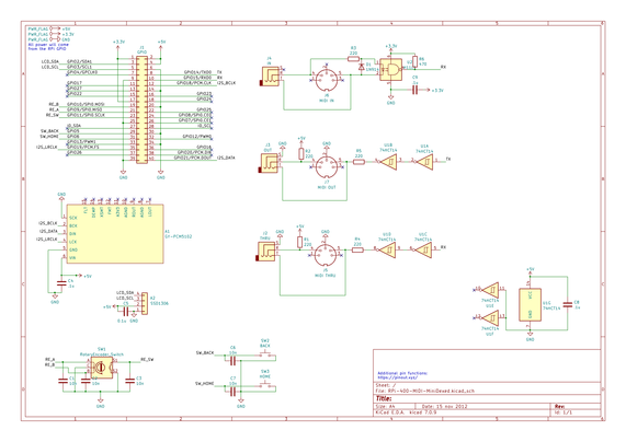
The key features of this design are:

  • Raspberry Pi 40 pin GPIO header connection.
  • Powered via the RPi GPIO.
  • Includes 3V3 MIDI IN circuit using H11L1.
  • Includes proper buffered MIDI OUT and THRU using 74HCT14.
  • Includes I2S connection to a GY-PCM5102 module.
  • Includes optional I2C SSD1306 OLED 32×128 display.
  • Includes optional rotary encoder and buttons with debouncing capacitors.

The primary aim for this board is Raspberry Pi 400 MIDI and I2S audio DAC. But I thought it I was going that far then I would also include the options for a rotary encoder, buttons and display which would allow the board to be used as a MiniDexed user interface too.

PCB Design

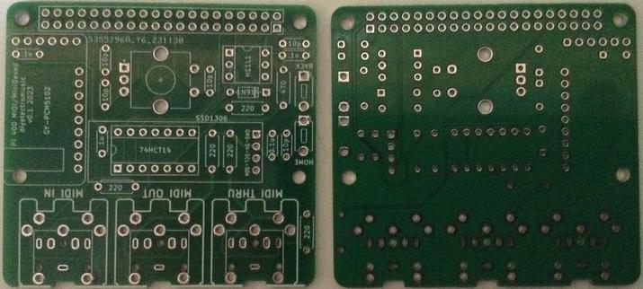
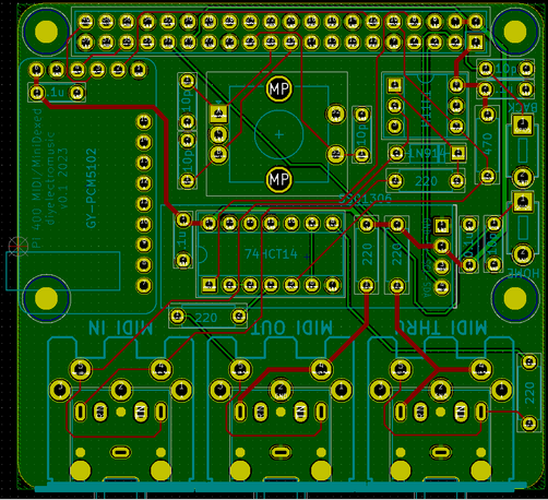
The board will plug in behind the RPi 400, so the idea is to use a 90-degree angle GPIO connector. The board supports either TRS or DIN MIDI sockets.

To just be used as a MIDI interface, the following components are required – all shaded out components may be omitted.

The I2S Audio DAC section is highlighted in purple on the left hand side if that is wanted to be added to the MIDI or just used on its own. Note how the capacitor for the PCM5102 will be situated between the PCB and the PCM5102 itself. It will need folding down to be installed.

This is a now standard (for my blog) H11L1 MIDI IN circuit paired with a 74HCT14 (not the HC variant – it has to be the HCT version to support the level shifting required) based MIDI OUT section. There is also a hardware MIDI THRU port. As can be seen from the PCB the board will take either TRS or DIN MIDI sockets – footprints are included for both.

Note: This is designed to be used with a right-angle GPIO header for plugging into a Raspberry Pi 400. Should the board want to be used with a typical RPi, then the power pins are on the far right hand side of the board with 5V on the top row and 3V3 on the bottom row. The GPIO connector will “point upwards” so it really has limited use with a normal Pi as all the components would be on the underside of the board – i.e. between the PCB and the Pi… but electrically it would all work!

To use the board as a MiniDexed user interface then the buttons, rotary encoder and SSD1306 display, and associated capacitors, can be added. Note that the SSD1306 display will have to sit above the 74HCT14.

There is one error on the board. All the debouncing capacitors for the encoder and the switches are labelled “10p” when it should be “10n”. I’ve made that mistake before and it simply got copied over to this design too without me spotting it!

Closing Thoughts

I was tempted to try to make something a bit simpler that could be used with my Cyberdeck, but instead opted for this stand-along board.

Whilst I don’t see a lot of use for a RPi-400 based MiniDexed, I couldn’t really think of a reason not to include the additional components. Having to route the PCM5102 such that the jack was in a useful position meant I wasn’t able to make the board much smaller anyway.

Kevin

https://diyelectromusic.wordpress.com/2023/12/18/rpi-400-midi-and-audio-pcb-design/

#midi #minidexed #pcb #pcm5102 #raspberryPi400
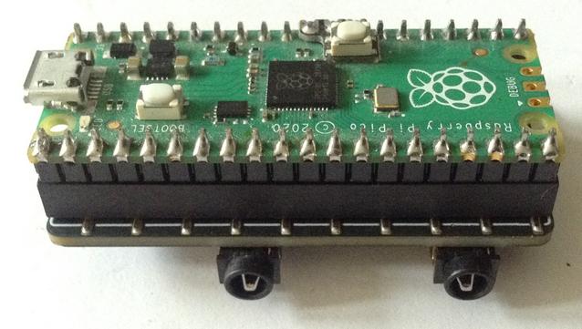
Raspberry Pi 400 Cyberdeck MIDI Player

I’ve finally gotten myself a Raspberry Pi 400 computer. I’ve wanted one for a while to use as a MIDI player for my Lo-Fi Orchestra. The idea is that eventually I might be able to run it…

Simple DIY Electronic Music Projects

Was laying out the #kicad #schematic for #muvco and it started to seem too pedestrian.

Went back and realized I had been using the #pcm5102 wrong and it does indeed do exactly what I originally wanted.

Now making a waveform generator instead of using the dds #ad9833. Much more flexible in shape and can be semi-polysynth ("chordal #synth"?) #synthdiy

Can now generate a perfect 5th in 260us! In mostly-unoptimized #micropython! Just dyads still--need to generalize to larger chords + diff shapes.

The nice thing about having a truly awful memory is that you have new ideas every day.

Hey, I thought, I should really try this #PCM5102 on the #esp32

After a few hours of frustration later, I got it working.

Then I found *my own review* on Amazon of this same device, rejecting it as having a problem that I now realize was me probably using it wrong.

If I could remember for more than 17.3us, I would never have tried this idea again.

So you see--a superpower.

The #PCM5102 also arrived and this one is even worse than #MAX98357. At least the 98357 accurately describes itself as a DAC + Class D amp. The 5102 just says it is a DAC but is also a Class D amp.

I guess the "generate waveforms" part of this project is on hold until next week. Instead, I can work on software I need to hook up all the bits.

It's the most useless #DTMF phone dialer! Only sequential numbers allowed!
(this is a test bed for doing multicore stuff on the #ESP32: #Mozzi audio synthesis in "loop()" on core1 and UI stuff on core0). Uses a @adafruit QTPy ESP32, a #PCM5102 I2S DAC, and a #SH1106 OLED display #Arduino code: https://github.com/todbot/mozzi_experiments/blob/main/esp32_multicore_mozzi_dtmf/esp32_multicore_mozzi_dtmf.ino #adafruit #qtpy
mozzi_experiments/esp32_multicore_mozzi_dtmf.ino at main · todbot/mozzi_experiments

Experiments with Mozzi, mostly on SAMD21 & RP2040 chips - mozzi_experiments/esp32_multicore_mozzi_dtmf.ino at main · todbot/mozzi_experiments

GitHub