Arduino with Multiple Displays – Part 2
As I mentioned in my last post on Arduino with Multiple Displays I’m going to look at other microcontrollers too. This post takes a wander through my Waveshare Zero and similar format boards that each support one of the RP2040, ESP32-C3 or ESP32-S3.
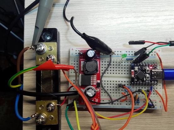
Warning! I strongly recommend using old or second hand equipment for your experiments. I am not responsible for any damage to expensive instruments!
These are the key Arduino tutorials for the main concepts used in this project:
If you are new to microcontrollers, see the Getting Started pages.
Parts list
- A Waveshare Zero format board or similar
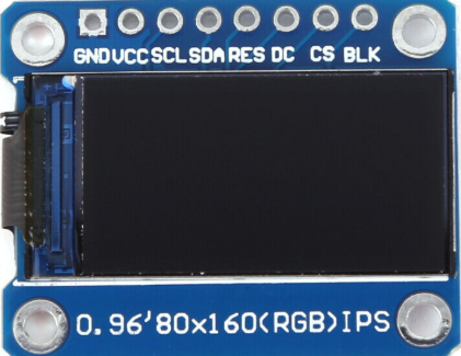
- 2x 0.96″ ST7735 60×180 SPI TFT displays.
- Breadboard and jumper wires.
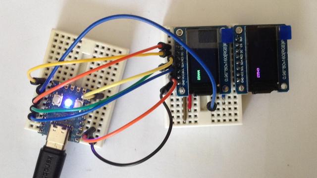
Once again I’m using displays that look like this – note the order of the pins.
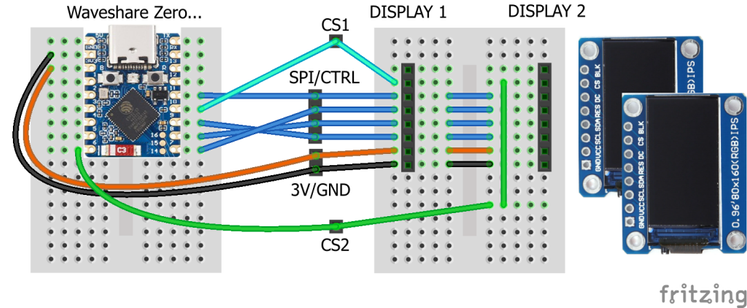
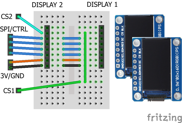
The Circuit
All circuits are a variation on the above, requiring the following ideal connections:
DisplayFunctionRP2040ESP32-C3ESP32-S3BLKBacklight control
(not required)N/CN/CN/CCSChip select
One per display.5 or any SPI0 CS1010DCData/Command888RESReset1499SDAData (MOSI)3 or any SPI0 MOSI6 or 711SCLClock (SCLK)2 or any SPI0 SCLK4 or 612VCCPower3V33V33V3GNDGroundGNDGNDGND
For the explanations of the pin choices, and what it means for the code, see the following sections.
ESP32-S3 Zero
In the Arduino IDE, using board ESP32-> Waveshare ESP32-S3-Zero.
There are several SPI buses on the ESP32-S3, but they have fixed uses as follows (see the ESP32-S3 Technical Reference Manual Chapter 30 “SPI Controller”):
- SPI 0: Reserved for internal use.
- SPI 1: Reserved for internal use.
- SPI 2: General purpose use – often called FSPI in the documentation.
- SPI 3: General purpose use – often called SPI or SPI3.
Sometimes the two SPI buses are called VSPI and HSPI but I think that is really terminology from the original ESP32 rather than the ESP32-S3.
The ESP32 Arduino core for the Waveshare ESP32-S3 Zero variant defines the following:
// Mapping based on the ESP32S3 data sheet - alternate for SPI2
static const uint8_t SS = 34; // FSPICS0
static const uint8_t MOSI = 35; // FSPID
static const uint8_t MISO = 37; // FSPIQ
static const uint8_t SCK = 36; // FSPICLK
By default the Adafruit libraries will use the boards default SPI interface, as defined in the variants.h file – i.e. the above.
When it comes to assigning SPI devices to GPIO there are a few considerations (see the “ESP32-S3 Technical Reference Manual, Chapter 6 “IO MUX and GPIO Matrix”):
- In general, any GPIO can be mapped onto any SPI function. However…
- Some GPIO have special “strapping” functions so are best avoided.
- Some GPIOs have a default SPI function that bypasses the GPIO MUX routing, so allows for better performance (see section 6.6 “Direct Input and Output via IO MUX”).
From my reading of the reference manual I believe the following are default “non-MUX” SPI connections:
In the previous table, where SPI3 is mentioned, then the entry for “Direct IO via IO MUX” is set to “no”, so I’m guessing that isn’t available.
But now we can see why the Arduino core is using GPIO 34-37, but we can also see that GPIO 10-13 would be an alternative (fast) option too.
The problem is that not all of GPIO 34-37 are broken out on a Waveshare ESP32-S3 Zero, so I need to use the alternative pinouts. Aside: this makes no sense to me that these are the defaults in the Waveshare ESP32-S3 Zero’s “variant.h” file, but anyway…
To use a different SPI interface requires using a constructor that passes in an initialised SPI instance. There is an example in the ESP32 core for setting up multiple SPI buses here: https://github.com/espressif/arduino-esp32/blob/master/libraries/SPI/examples/SPI_Multiple_Buses/SPI_Multiple_Buses.ino
This leads to the pins as defined in the previous table, and the code below to setup one of the displays.
#include <Adafruit_GFX.h> // Core graphics library
#include <Adafruit_ST7735.h> // Hardware-specific library for ST7735
#include <SPI.h>
#define SPI_SS 10
#define SPI_MOSI 11
#define SPI_SCLK 12
#define SPI_MISO 13
SPIClass MySPI(FSPI);
#define TFT_CS SPI_SS
#define TFT_RST 9
#define TFT_DC 8
Adafruit_ST7735 tft = Adafruit_ST7735(&MySPI, TFT_CS, TFT_DC, TFT_RST);
void setup() {
MySPI.begin(SPI_SCLK, SPI_MISO, SPI_MOSI, SPI_SS);
pinMode(SPI_SS, OUTPUT);
tft.initR(INITR_MINI160x80_PLUGIN);
}
ESP32-C3 Zero
In the Arduino IDE, using board ESP32-> ESP32C3 Dev Module.
Again there are several SPI buses on the ESP32-C3, with the same fixed uses as follows (see the ESP32-C3 Technical Reference Manual Chapter 30 “SPI Controller”):
- SPI 0: Reserved for internal use.
- SPI 1: Reserved for internal use.
- SPI 2: General purpose use – sometimes called GP-SPI in the documentation.
The ESP32-C3 also has a very similar SPI arrangement to the ESP32-S3, in that whilst any pin can be configured for SPI usage, there are certain hard-wired optional arrangements that bypass the GPIO routing matrix.
The faster (direct to IO MUX) pins are as follows (more here):
- CS0 – 10
- SCLK – 6
- MISO – 2
- MOSI – 7
Curiously, the general ESP32-C3 Arduino variant defines them as follows:
static const uint8_t SS = 7;
static const uint8_t MOSI = 6;
static const uint8_t MISO = 5;
static const uint8_t SCK = 4;
From the Technical Reference manual, we can see that the default Arduino definitions above, do not support the non-routed, direct-to-IO MUX pin mappings, which from the table below do indeed map onto GPIO 2, 6, 7, 10.
In terms of using a Waveshare ESP32-C3 Zero, both combinations would be supported on the broken out GPIO, so from a software point of view, the Adafruit libraries could be used “as is” with the default mapping, or with a custom SPI definition (as shown above) with the more bespoke, but faster, mapping.
RP2040 Zero
This is using the (unofficial) RP2040 core from here: https://github.com/earlephilhower/arduino-pico, where this is an entry: RP2040 -> Waveshare RP2040 Zero.
The RP2040 has two SPI peripherals and the SPI functions are mapped onto specific sets of GPIO pins. This gives a range of flexibility, but not arbitrary flexibility. The board definition file for the Waveshare RP2040 Zero provides this as a default:
// SPI
#define PIN_SPI0_MISO (4u)
#define PIN_SPI0_MOSI (3u)
#define PIN_SPI0_SCK (2u)
#define PIN_SPI0_SS (5u)
#define PIN_SPI1_MISO (12u)
#define PIN_SPI1_MOSI (15u)
#define PIN_SPI1_SCK (14u)
#define PIN_SPI1_SS (13u)
Note that the SPI1 pins for the Waveshare RP2040 Zero are not all on the standard header connections, some are on the additional pin headers across the bottom.
Using a bespoke configuration is possible using a series of calls to set the SPI pins as shown below.
SPI.setRX(SPI_MISO);
SPI.setCS(SPI_SS);
SPI.setSCK(SPI_SCLK);
SPI.setTX(SPI_MOSI);
SPI.begin(true);
To use pins for SPI1, replace SPI above with SPI1. As long as this happens prior to the call to the Adafruit libraries, everything works fine.
A Common Option
It would be nice to find a set of physical pin connections that I know would always work regardless of the board in use: RP2040, ESP32-S3 or ESP32-C3.
With careful noting of the RP2040 limitations, I think that is largely possible with the following. Even though the GPIO numbers are different, the physical pins are common on all three boards.
DisplayFunctionWS PinRP2040ESP32-C3ESP32-S3BLKBacklight control
(not required)N/CN/CN/CCS1Chip select
Display 1H2 P6GP5GP9GP10DCData/CommandH2 P5GP4GP10GP11RESResetH2 P9GP8GP6GP7SDAData (MOSI)H2 P8GP7GP7GP8SCLClock (SCLK)H2 P7GP6GP8GP9VCCPowerH1 P33V33V33V3GNDGroundH1 P2GNDGNDGNDCS2CS Display 2H1 P9GP14GP5GP6CS3CS Display 3H1 P8GP15GP4GP5CS4CS Display 4H1 P7GP26GP3GP4
A couple of notes:
- I’ve avoided pins 1-4 on header 2, as the ESP32-C3 can’t use them for SPI and they support either the UART or USB.
- I’ve had to include a MISO (SPI RX) pin in each configuration too, so I’ve just picked something that can be ignored. For RP2040 that has to be one of GP0, GP4 or GP16 however, which could clash with either the UART, the above configuration for DC pin, or the onboard WS2812 LED, but there isn’t much that can be done.
- I’ve allowed three consecutive pins on the first header for optional additional CS pins for displays 2 to 4.
Here is the full set of configurable code for the above:
#include <Adafruit_GFX.h> // Core graphics library
#include <Adafruit_ST7735.h> // Hardware-specific library for ST7735
#include <SPI.h>
//#define WS_RP2040_ZERO
//#define WS_ESP32C3_ZERO
#define WS_ESP32S3_ZERO
#ifdef WS_RP2040_ZERO
#define SPI_SS 5
#define SPI_MOSI 7
#define SPI_SCLK 6
#define SPI_MISO 4 // Not used
#define SPI_BUS SPI
#define TFT_CS1 SPI_SS
#define TFT_CS2 14
#define TFT_CS3 15
#define TFT_CS4 26
#define TFT_RST 8
#define TFT_DC 4
#endif
#ifdef WS_ESP32C3_ZERO
#define SPI_SS 9
#define SPI_MOSI 7
#define SPI_SCLK 8
#define SPI_MISO 0 // Not used
SPIClass MySPI(FSPI);
#define TFT_CS1 SPI_SS
#define TFT_CS2 5
#define TFT_CS3 4
#define TFT_CS4 3
#define TFT_RST 6
#define TFT_DC 10
#endif
#ifdef WS_ESP32S3_ZERO
#define SPI_SS 10
#define SPI_MOSI 8
#define SPI_SCLK 9
#define SPI_MISO 1 // Not used
SPIClass MySPI(FSPI);
#define TFT_CS1 SPI_SS
#define TFT_CS2 6
#define TFT_CS3 5
#define TFT_CS4 4
#define TFT_RST 7
#define TFT_DC 11
#endif
#ifdef WS_RP2040_ZERO
Adafruit_ST7735 tft1 = Adafruit_ST7735(TFT_CS1, TFT_DC, TFT_RST);
Adafruit_ST7735 tft2 = Adafruit_ST7735(TFT_CS2, TFT_DC, -1);
#else
Adafruit_ST7735 tft1 = Adafruit_ST7735(&MySPI, TFT_CS1, TFT_DC, TFT_RST);
Adafruit_ST7735 tft2 = Adafruit_ST7735(&MySPI, TFT_CS2, TFT_DC, -1);
#endif
void setup() {
#ifdef WS_RP2040_ZERO
SPI_BUS.setRX(SPI_MISO);
SPI_BUS.setCS(SPI_SS);
SPI_BUS.setSCK(SPI_SCLK);
SPI_BUS.setTX(SPI_MOSI);
SPI_BUS.begin(true);
#else
MySPI.begin(SPI_SCLK, SPI_MISO, SPI_MOSI, SPI_SS);
pinMode(SPI_SS, OUTPUT);
#endif
tft1.initR(INITR_MINI160x80_PLUGIN);
tft2.initR(INITR_MINI160x80_PLUGIN);
tft1.setRotation(3);
tft1.fillScreen(ST77XX_BLACK);
tft2.setRotation(3);
tft2.fillScreen(ST77XX_BLACK);
}
void loop() {
unsigned long time = millis();
tft1.fillRect(10, 20, tft1.width(), 20, ST77XX_BLACK);
tft1.setTextColor(ST77XX_GREEN);
tft1.setCursor(10, 20);
tft1.print(time, DEC);
delay(100);
time = millis();
tft2.fillRect(10, 20, tft2.width(), 20, ST77XX_BLACK);
tft2.setTextColor(ST77XX_MAGENTA);
tft2.setCursor(10, 20);
tft2.print(time, DEC);
delay(400);
}
Closing Thoughts
It is a little annoying that these great boards don’t share a re-usable, common pinout in terms of naming and positions, but I guess that isn’t the main focus for these systems.
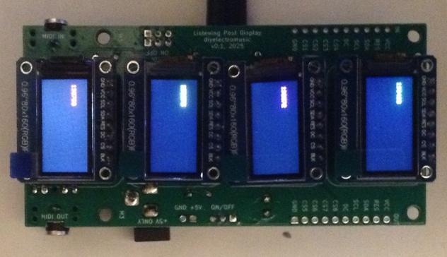
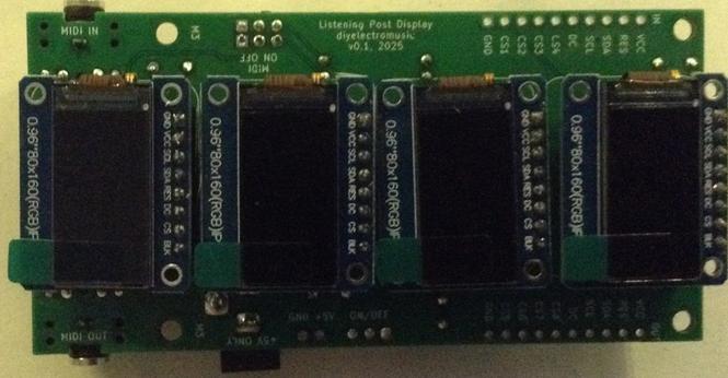
Still, it seems that a common hardware pinout can be made that supports many displays, which is great, as I’d really like to get a number of them onto a PCB!
Kevin
#arduinoUno #esp32c3 #ESP32s3 #rp2040 #st7735 #tftDisplay #WaveshareZero