Just putting this out there but I'm now using #ESP32S3 minis instead of #ESP32C3 minis with @microblocks as I find they much more reliably connect to my home WiFi. (Yes I know about the new C3 antenna variants but decided a just want a compact simple thing that just works without having to worry about whether it will or not)
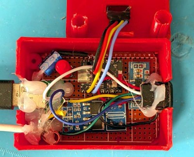
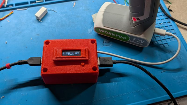
ChargeCap Helps Your Batteries Last Longer By Limiting Charge Level