I made a thing! For those 3-4 people in the Fediverse who tinker with #Nascom and #GeminiMicrocomputers, I present: The 80-Bus Stop - convernient and safe storage for your 8x8" expansion cards. Enjoy ;-)
@stepleton I've got some old CP/M disks for the #GeminiMicrocomputers Galaxy system that may be worthy contentants?

Here's a weird thing I found, while restoring my old #CPM computers from #GeminiMicrocomputers: while there were models available with Winchester drives (that's harddisks for you young folks), the setup was a little weird. This was the time of the #MFM and RLL harddrives, used by other systems such as the IBM 5150. Easily recognizable by having two flat ribbon cables instead of just one for each drive. RLL was a little more tightly packed with capacity, but basically the same concept - required slightly different controllers though.
Anyway, back to the Gemini. It featured a #SASI interface, which is sort of an early version of #SCSI. Did you connect a drive directly to it? Noooo. You connected a #Xebec SCSI/MFM controller. Did that require a lot of weird SCSI commands for telling the Xebec what disk was attached? Of course. Compared to how it's done today, very backwards.
Which meant I had zero luck with my new #zuluscsi device. https://zuluscsi.com/
I've got a plan B though.
ZuluSCSI - A hardware SCSI HDD & CD-ROM emulator
ZuluSCSI® is a SCSI computer storage emulation platform, which speaks both SCSI-1 and SCSI-2. It uses file-based SCSI HDD & CD-ROM images. New for 2025, **ZuluSCSI Blaster** leverages the new RP2350B, which includes additional I/O capabilities, including optional Red Book CD Audio playback and Wi-Fi Ethernet for compatible classic Macintosh...
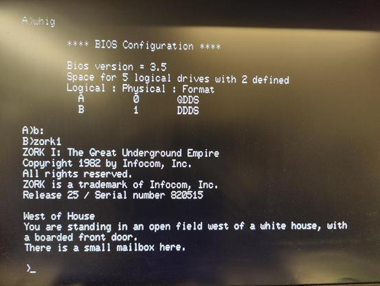
Anyone up for a game of #Zork on a GM905 system from #GeminiMicrocomputers featuring a #z80 processor, 64K memory and dual #gotek floppy emulators running #FlashFloppy? Eh? 😜
Is your 40+ years old #vintagecomputer suffering from ribbon cable bird's nest syndrome? Don't delay! Print my ribbon cable chassis connector housing thing today! 🙂 Also, be gentle - I'm new to #3d :-)

Ribbon cable chassis housings for DB9/DB15/DB25/Centronics connectors by saustrup
While restoring an old CP/M system, I found that one of the most fragile parts were the IDC-to-DB25 and IDC-to-Centronics ribbon cables that went from the various expansion cards to the chassis. Not the simple 1:1 crimped cables, but the ones with Centronics or DB-25 connectors soldered by hand, for instance for RS-232 or parrallel printer ports. These are often a bit of a birds nest, with a couple of wires taking most of the load if the cable is accidentally pulled.These inside-the-chassis connector housings should fix the issue.For the best fit, print a connector with the proper number of ribbon cable wires.Screw holes are all the way through, as it has proven difficult to get supports out otherwise.Parts needed:DB connectors:2 x 3x10M screws2 x 3M nutsCentronics connectors:2 x 2.5M screws2 x 2.5M nutsSource is available on Github here: https://github.com/hcsaustrup/3d-openscad/tree/main/RibbonCableChassisHousings
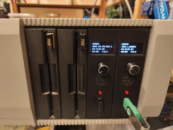
It's done! I figured "if you're gonna build a old school vertical #gotek enclosure, why not do it with some style?". I'm aiming for that early 80s style, and I'm quite happy with the result, although the OLED sticks out a bit. It is terribly practical for navigating disk images though. What do you think?
Video of the unit booting CP/M in thread.
Model available here: https://www.thingiverse.com/thing:6939095


Gotek 5.25" Vertical Mount by saustrup
This is a 3-part enclosure/case/mount for a Gotek floppy emulator running the FlashFloppy firmware. It's designed to match the style of early 80s microcomputers, with the OLED being a noticeable but rather convenient exception.If you build and use this in an old system, please post pictures! :-)Parts needed:1 x Gotek floppy emulator (see photo - unsure if other versions will fit - please report back)1 x 1.3" I2C 128x64 monochrome OLED display (the one with a 4-pin header at the top - available on AliExpress etc.)1 x Rotary encoder with 12x12mm body (model without nudge/peg)1 x 5mm red LED1 x 27mm piezo buzzer4 x M3x6 screws (for mounting the OLED cover)5 x M3x6/8 screws (for mounting the PCB)3 x M3x5 sunken head screws (for mounting the PCB tray to the case)Wires for connecting everythingAssembly:Prepare PCB (remove from case, remove original LED, optionally solder in pin headers)Attach OLED display and secure with the OLED cover pieceAttach components to base (rotary encoder, piezo buzzer, LED)Mount PCB on tray and attach to baseFor details on connecting the components, see https://github.com/keirf/FlashFloppy/wiki/Hardware-Mods
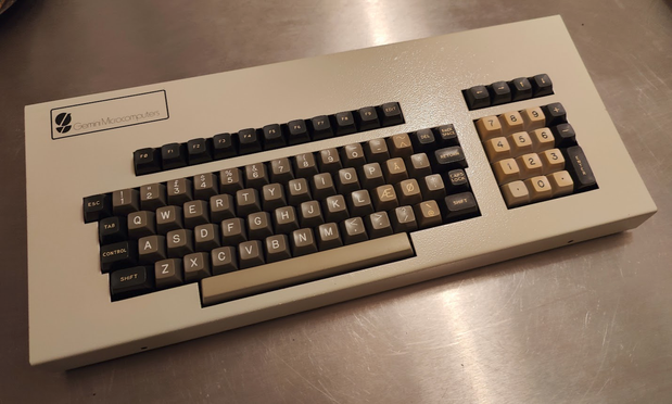
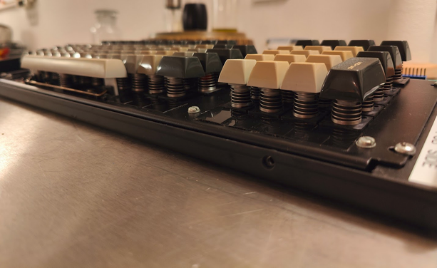
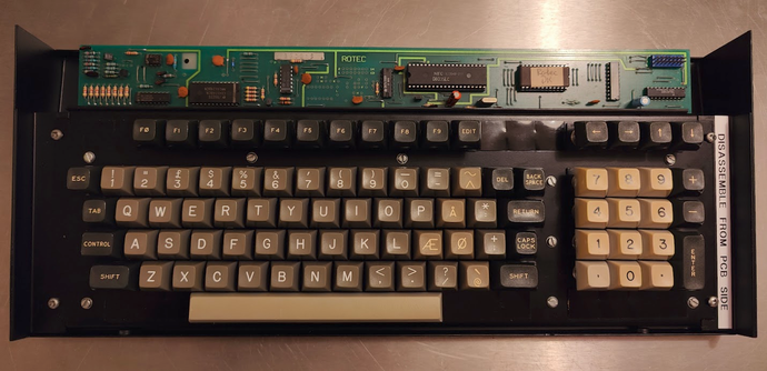
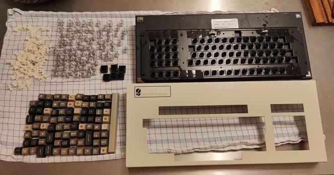
As promised: a complete deep clean of the late #70s #GeminiMicrocomputers parallel #keyboard by #Rotec. Everything disassembled, cleaned, lubed, rubber liners treated with silicone and brand new rubber feet installed. All keys are working, but some don't sit as well in their sockets as they used, so I expect the keys to stay in place if I hit someone with it! :D Also some electrical issues with scanning of the key matrix being incredibly slow - but it lives!! 🙂
And yeah, the "DISASSEMBLE FROM PCB SIDE" sticker was added by me. Taking this apart the wrong way will end in disaster. Learned that the hard way.
No spiders were hurt in this cleaning, although they had clearly taken up residency at some point.
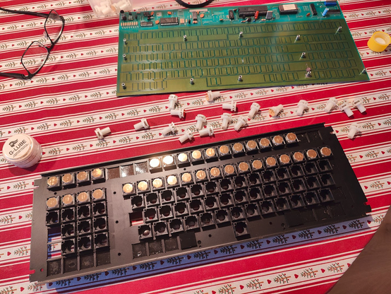
First bath in 42 years. Much needed.
#vintagecomputing #GeminiMicrocomputers #keyboards #80s #norgb
I'm designing a 5.25" front for the Gotek floppy emulator that will go in my #GeminiMicrocomputers. It's vertical, has a #rotaryencoder, a 1.3" OLED display and a big fat red 5mm LED. I think it's going to look sort of period correct, if you disregard the presence of the OLED.
And yeah, this is a test run so dimensions are minimal and color is whatever was on the #Prusa #3dprinter.


