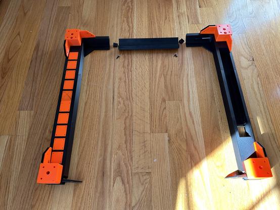
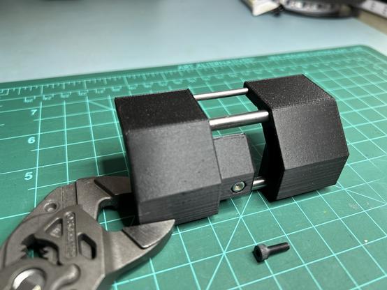
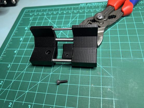
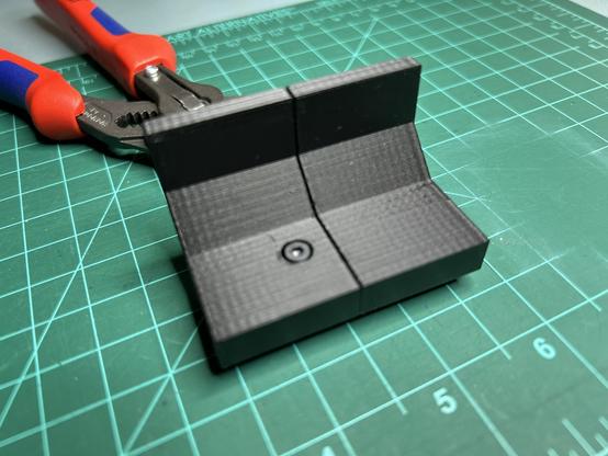
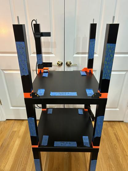
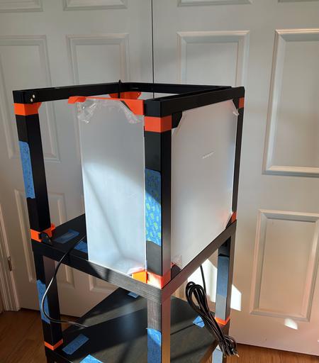
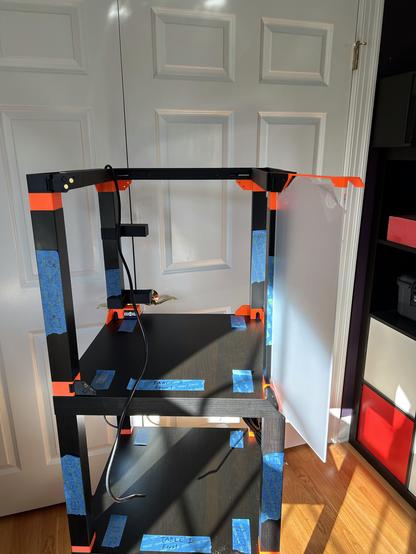
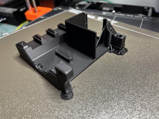
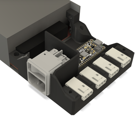
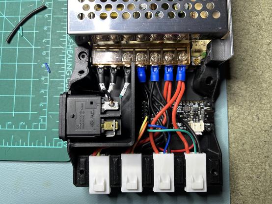
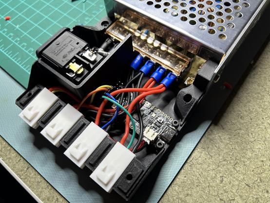
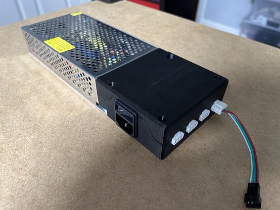
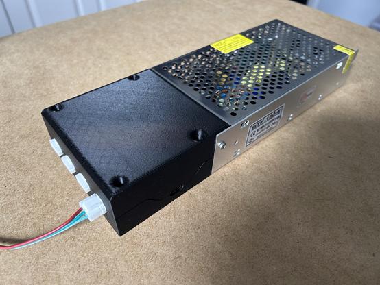
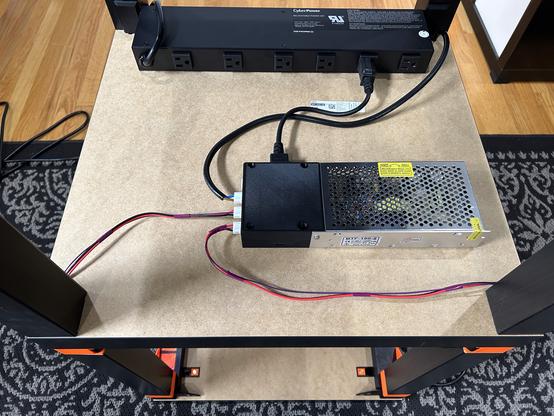
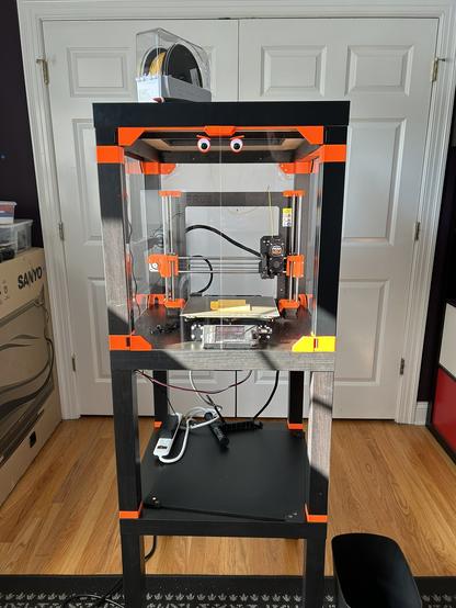
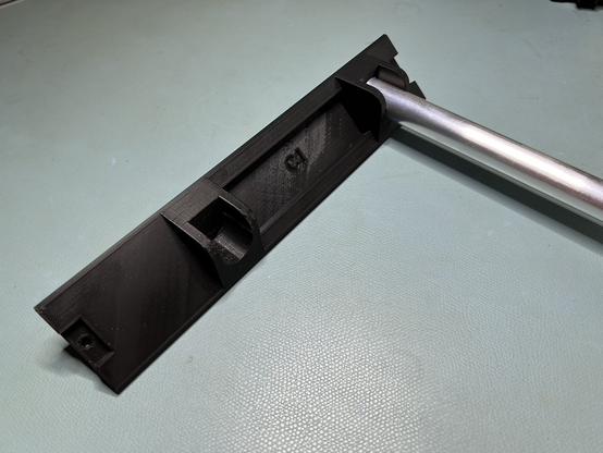
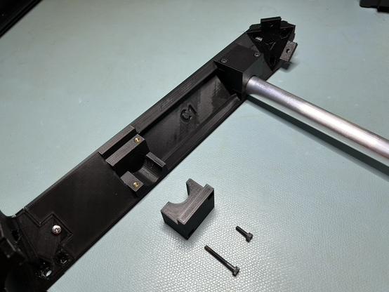
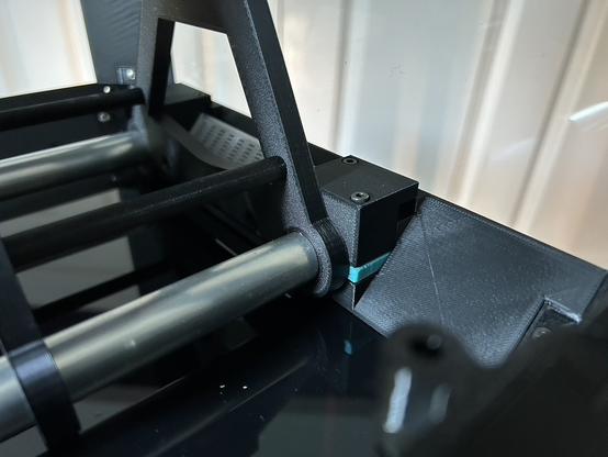
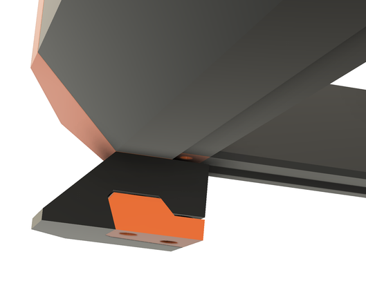
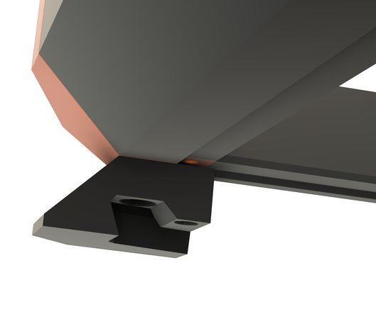
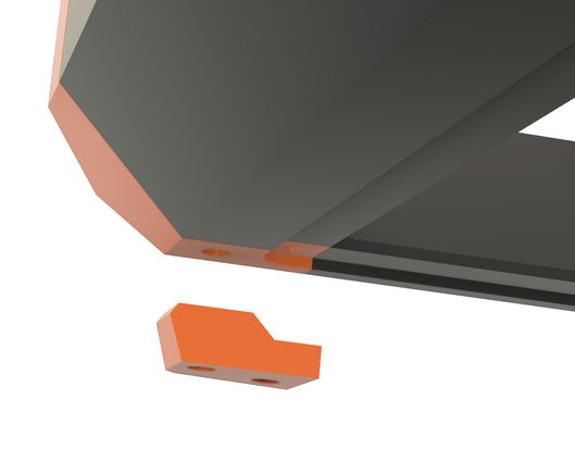
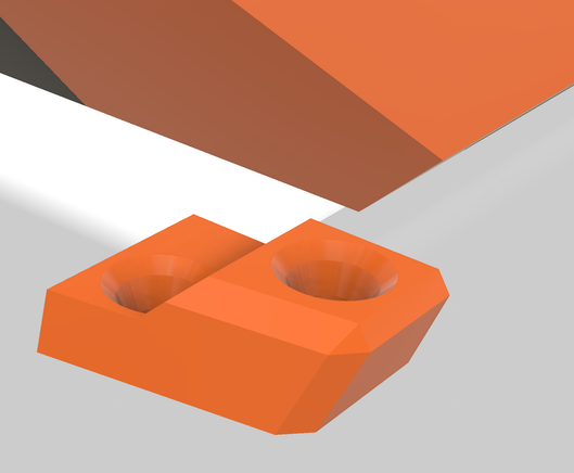
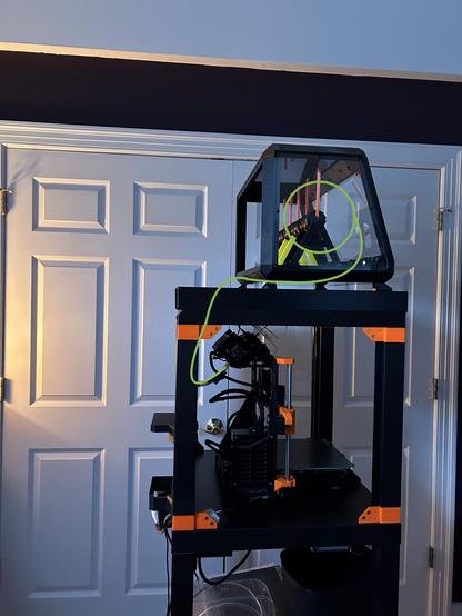
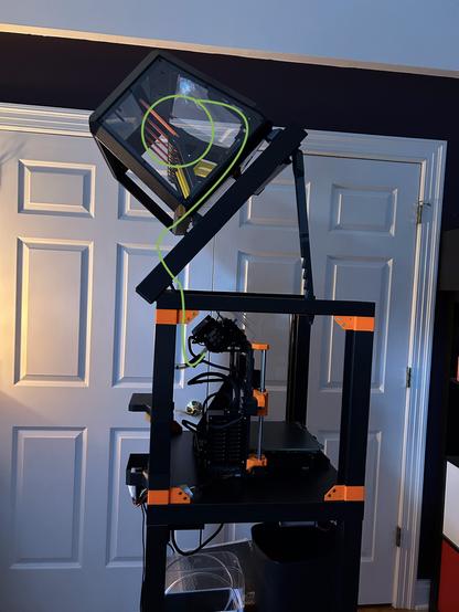
@3dprinting After all the progress I've made on the Black Lack Stack Hack recently, I was due for a setback. I carelessly picked this assembly up by one end to show it to someone, and it cracked under its own weight. When it hit the floor, the opposite joint cracked too.

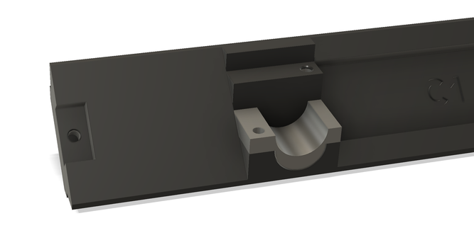
They were wobbly anyway, so I should design something better.

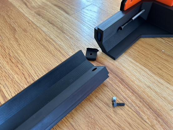
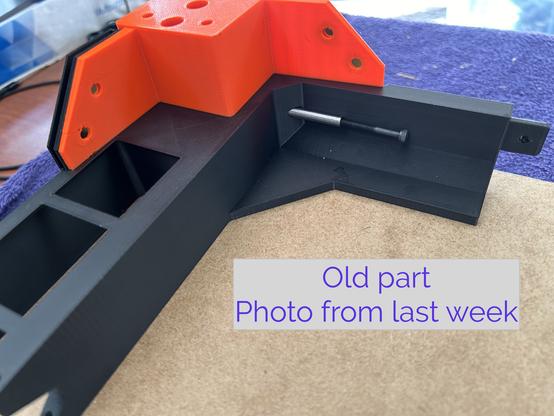
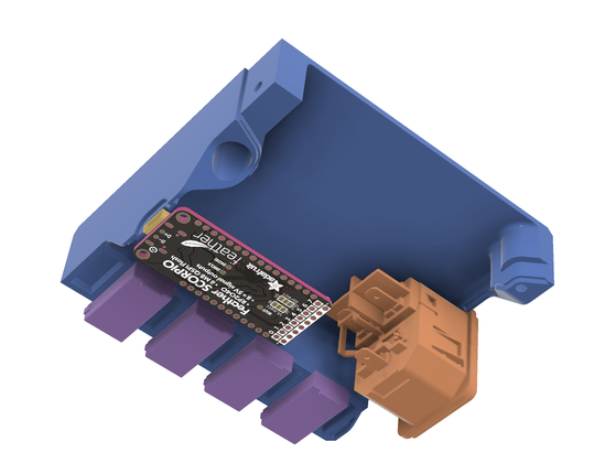
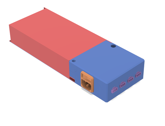
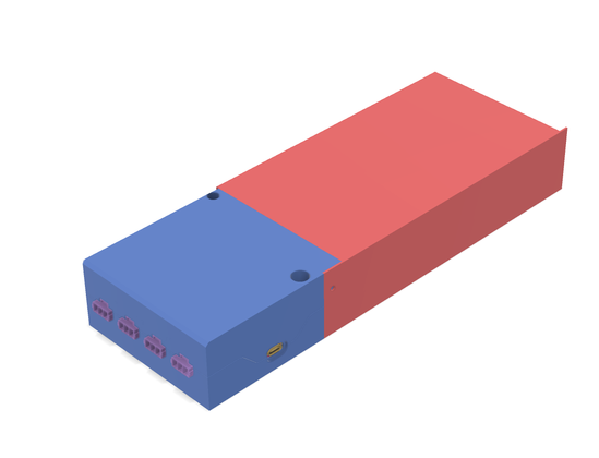
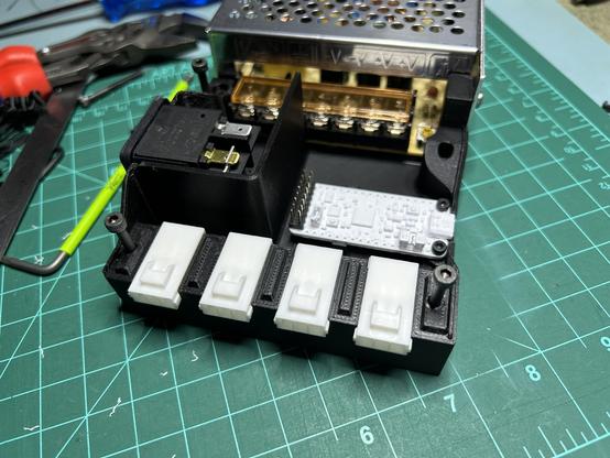
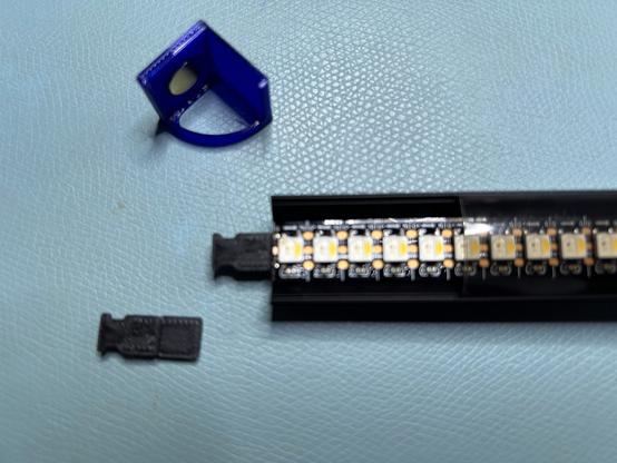
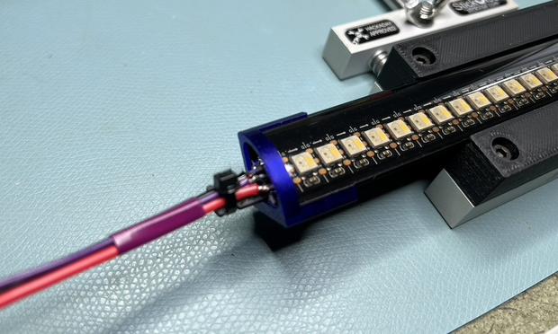
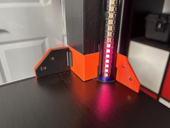
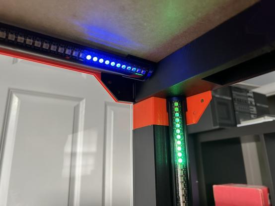
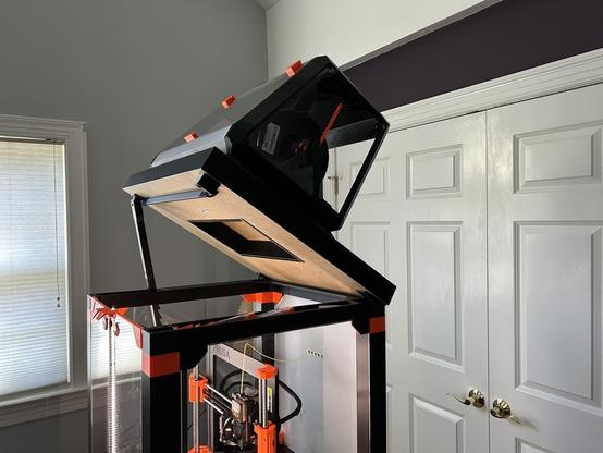
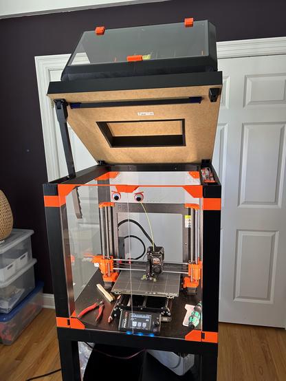
Edit: two more photos.

#BlackLackStackHack #Prusa3D

@3dprinting I spent yesterday designing a new joint. I ended up using a bigger mortise/tenon plus three dowel pins. (I really love dowel pins.) The pins are 5x50mm and 3x30mm. The screw is M3x10.

I printed these two test pieces to verify fit. They are plenty rigid, and I have to pry them apart with a screwdriver. This is definitely overengineered. (I really love overengineering things.)

#BlackLackStackHack #Prusa3D

@3dprinting The bad news is that the two parts that broke are the two longest-printing parts in the whole enclosure. Reprinting all three parts is about 15 hours. Fortunately, I started last night...

#BlackLackStackHack #Prusa3D

@3dprinting One more layer. The cord at the back left is for the addressible LED strip in the lid. It was a pain to fish through. It is a power cord with the ends snipped off; I'll crimp on some JST SL connectors later.

I've been looking at the CAD drawing for so long that it doesn't even look like a new thing.

#BlackLackStackHack #Prusa3D

@3dprinting One more layer. I test fit one door and one window. Each door is held on by 4 magnets and has another four keeping it closed. Each window is held on by 8. The windows have just the right amount of magnetic glomp (technical term). The door is kind of wobbly but it stays closed.

I have errands for the rest of the day, so the lid will have to wait.

#BlackLackStackHack #Prusa3D

@3dprinting I think if I wanted to improve the door action, I'd make it so the closure magnets are further apart. They are too strong, so the door slams.

@3dprinting I amuse myself.

The precut acrylic pieces came with holes for door handles, but I didn't like the handles they suggested. So I made these.

Note that there's still no printer in this alleged printer enclosure.

#3DPrinting #BlackLackStackHack #Prusa3D

@3dprinting I put the eyes on long, thin stalks and added a machine screw for weight. Hopefully, when the printer starts the cabinet vibrating, they eyes will jiggle. We'll see.

#BlackLackStackHack #Prusa3D #3DPrinting

@3dprinting I'm working on the LED strip power supply for my printer enclosure.

I've been pondering the layout of these parts for a while. Last night I got the power entry units, and I spent the whole day today coming up with this. It's nowhere near done, but it shows the general layout. I'll split the blue part into two halves suitable for printing somehow.

I should have bought a power supply with a power plug integrated.

#BlackLackStackHack #Prusa3D #WS2812

@3dprinting Yeah, so, the Feather SCORPIO. It's based on a RP2040, and it has eight 5V outputs for driving addressable LEDs. I only have 195 LEDs, but it makes the wiring easier to have three short strips instead of one daisy chained strip.

I'm putting in four JST connectors in case I want MOAR LEDS!!!! later.

#BlackLackStackHack #WS2812 #LEDs #RP2040

@3dprinting Here's what I came up with. First picture shows the bottom half with components attached. Second pic is the top half.

I just started printing it; I'll see what doesn't fit.

I'm grateful that Adafruit publishes CAD models of their boards.

#BlackLackStackHack #WS2812 #LEDs

@3dprinting I put in a partition to isolate the 120V power from the low voltage stuff. It's not a perfect seal, but it'll probably keep my fingers safe.

#BlackLackStackHack #yikes

@3dprinting I printed three iterations of the bottom half yesterday and one of the top half. Today I spent a solid 16 hours in Fusion360 tweaking the design -- why is F360 so tedious and manual? Every time I changed anything at all, I had to redo the flanges where the case halves meet.

This should be pretty close to finished, so I'm using the good filament.

#BlackLackStackHack #Fusion360 #WS2812 #LEDs

@3dprinting Everything fits perfectly. The top half is printing now.

(Yes, that's a 3D printed stand-in for the controller board. Adafruit published an STL. It has 0402 components, and they came out more 0402-shaped than blob-shaped. But the connectors cracked when I removed the supports.)

I'm running out of ways to procrastinate crimping the cables. I do not enjoy crimping.

#BlackLackStackHack #WS2812 #LEDs #3DPrinted

@3dprinting The next challenge was attaching leads to the LED strips. I glued this 144/meter RGBW strip into this aluminum channel. I'd printed end caps with embedded magnets (the aquamarine parts). I'd drilled holes through the table to run the leads down to the power supply (previous post). But the solder tabs on the strip are tiny, and I'd made no provision for strain relief.

This is what I came up with. I've assembled one, and it seems to be okay.

#BlackLackStackHack #LEDs #WS2812

@3dprinting The cable tie will be inside the hole in the table when this is in place. There's room, because this assembly is smaller than the connector on the cable end.

I printed tall jaws for the StickVise to hold the aluminum channel, of course.

#BlackLackStackHack #LEDs #WS2812 #HackADay

@3dprinting This strip will run vertically up the left side of the cabinet. Another will run up the right side and will be just the same. I don't know what I'm going to do for the strip across the ceiling, because there's no room on either end for anything. I'd assumed I'd run the leads straight up somehow, didn't really start thinking about how to attach the leads until yesterday. I've got 1.5 or 2 mm of space on each end, I think.

#BlackLackStackHack #PlanningIsForOtherPeople

@3dprinting I never posted photos of the LED power supply after wiring. Here are some photos of the LED power supply after wiring.

Everything unplugs or unscrews except the wires on the power inlet module.

#BlackLackStackHack #3DPrinted #LEDs #WS2812

@3dprinting And here it is with the lid on. It looks remarkably unremarkable, just another power supply thing.

#BlackLackStackHack #LEDs #WS2812 #3DPrinted

@3dprinting The LED controller and light bars are installed into the enclosure. FInally. Hooray!

I am very pleased with the way they came out, though I worry that the top bar is fragile. There's no strain relief on the cable; it's just hanging on by its solder joints.

I might tack the wires up to the underside of the table later, but for now, they're staying in place just by their own stiffness.

#BlackLackStackHack #LEDs #WS2812

@3dprinting Here's a test pattern, viewed from the back. From the front and sides, you can't see the LEDs directly.

#BlackLackStackHack #LEDs #WS2812

@3dprinting That test pattern uses golden ratio colors to generate apparently random but pleasing color sequences. It's a pretty cool technique which I just re-learned about. This 'blog post describes it pretty well.

https://martin.ankerl.com/2009/12/09/how-to-create-random-colors-programmatically/

#BlackLackStackHack #WS2812 #LEDs

How to Generate Random Colors Programmatically

Creating random colors is actually more difficult than it seems. The randomness itself is easy, but aesthetically pleasing randomness is more difficult. For a little project at work I needed to automatically generate multiple background colors with the following properties: Text over the colored background should be easily readable Colors should be very distinct The number of required colors is not initially known Naïve Approach The first and simplest approach is to create random colors by simply using a random number between [0, 256[ for the R, G, B values. I have created a little Ruby script to generate sample...

Martin Leitner-Ankerl

@3dprinting The LEDs have firmware now. I made a short video that puts them through their paces -- they have modes that match the LEDs on the MK4's front panel, but with more flair. I have no idea how to sync up with the printer's state yet. I'm assuming Octoprint will make that possible somehow.

https://makertube.net/w/f6QzhDstn7zJ7S2KHP7QWS

#BlackLackStackHack #octoprint #LEDs

LED Demo - Black LACK Stack Hack

PeerTube

@3dprinting Yesterday I _finally_ put the printer into the enclosure. After a few hours debugging a badly assembled power connector, it's up and running.

This enclosure is far from finished, but I was having trouble with air currents in my office ruining prints.

#BlackLackStackHack

@3dprinting I decided it was time to redesign the googly eyes on the printer enclosure. (See upthread at June 19th.)

a) they don't wobble as intended
b) they stick out and get in the way of the door handles
c) they rotate freely in the round holes and the eyebrows are always at weird angles
d) I dropped one of the doors and broke an eye stalk.

🧵 60(?)/∞

#BlackLackStackHack

@3dprinting

This time, the googly is a multi piece assembly that screws tightly onto the door. No wobbling, no protrusion, no rotation.

Note the place to insert an 8mm Allen wrench to hold the eye in alignment during assembly. The eye is held onto the orange bit with double sided Scotch tape.

🧵 61/∞

#BlackLackStackHack

@3dprinting I'm adding an (Un)original Prusa Drybox to my printer enclosure's lid, along with auto-rewinders. (Thanks to @GavinCampbell for the tip.)

The drybox uses lots of heat set inserts, so I completed a side quest to build an insert press. Now I'm back.

🧵 62/∞

#BlackLackStackHack

@3dprinting I'm trying to resist the urge to mod the drybox, but I'm putting the drybox on the printer's lid, and the lid tilts past 90°. So I need a way to keep the rails from falling out.

The original is in the first photo; my version is the second.

🧵 63/∞

#BlackLackStackHack

@3dprinting

The autorewinder adapter for the (Un)original Prusa Drybox did not fit. The sleeves that surround the rail are too thick, and they keep the bottom cover from going on.

This isn't an issue for other users; they just let the rails ride higher in their slots. But I screwed my rails down.

So I added a shim under each rail. (It's teal in the photo.) It's temporary; I'll eventually redraw the sleeves so they fit.

🧵 64/∞

#BlackLackStackHack

@3dprinting Actually, the sleeve thickness is a problem for other people. The rails and therefore the filament spools, up to 5kg, are resting on the bottom panel, putting high stress on the screw holding it up.

🧵 65/∞

#BlackLackStackHack

@3dprinting The (Un)original Prusa Drybox is installed. I made feet, and the front feet engage little cleats. They're not exactly French cleats, but they're francophone.

🧵 66/∞

#BlackLackStackHack #UnoriginalPrusaDryBox

@3dprinting The cleats hold the drybox on even when the lid is tilted.

But when I tilted the lid all the way up, just past vertical, the box fell off. So I shouldn't do that. I'd need bigger cleats or a different angle of engagement.

🧵 67/∞

#BlackLackStackHack #UnoriginalPrusaDryBox

@3dprinting Here are some renders of the foot and cleat. The back feet don't have cleats; they just rest on the lid.

🧵 68/∞

#BlackLackStackHack

@3dprinting Now that I have an MMU, I am thinking about how to route the PTFE tubes from the drybox to the MMU. My original plan, before I saw how far back the MMU sits, was to route it through the lid. Something like the green line here.

But that wouldn't work. The cable is kinked way too tightly.

🧵 69/∞

#BlackLackStackHack #MMU3 #Prusa

@3dprinting Prusa's solution looks like this. Five holes in the back window.

I don't like that because the window is no longer removable without unthreading the tubes. My intention is to make it possible to install/remove the windows while printing or remove the printer and drybox, separately, without tools.

But the routing is much cleaner.

(Photo by Ondřej Stříteský)

🧵 70/∞

#BlackLackStackHack #MMU3 #Prusa

@kbob why not make comb style notches at the top of the window? The window is removable and you don't need any complicated mechanics to accomplish that.
@esden I think that would be too high. The tubes have to be low to have the right entry angle to the MMU.
@kbob You can move the holes lower by introducing interlocking fingers from the top to fill the gaps between the “comb" teeth. If this starts becoming flimsy you might need to add some features that keep the fingers from flapping around when you slot them in. Still it might be a relatively simple solution all things considered.
@esden You're saying something like this?
@kbob Yeah exactly. Alternatively you can make it one tab that comes down from the top. But maybe it is good enough if you leave the slots just open?

@esden Well, the enclosure is supposed to enclose the printer. It's far from airtight, but it does get a lot warmer than the outside air, and adding a big vent would keep it from getting as warm.

I have not added a heater, though I've thought about it. That's an even bigger project...

@kbob will the narrow slots be such a big impact? If it is you can have tabs that cover up those slots. There are many ways of making that particular solution work. But it is also only one solution out of many.
@esden That's kind of what I did in the sketch. The orange piece is there to protect the edge of the panel and hold the magnets, and the green piece covers the big hole.
@kbob It just seems a bit complicated with all the magnets and frames compared to a few laser cut slots. That said, just doing some remote arm chair engineering here. You know better what will work for you. :)