If I make another one, I'm going to change pretty much everything except the colour.
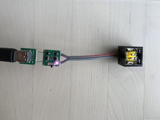
This build was a bit of a washout overall, but since the boards are made up of distinct modules connected by wide traces it’s very easy to break it down and reuse bits. Here’s the usb segment & battery charger segment from one of the casualties charging a little Lego clip-on battery.
The first two boards from this batch powered up just fine. The next one was dead, and I thought maybe I saw smoke? The next one let the smoke out immediately. I stopped plugging them in after that while I tracked down what was going on. It turns out that for one of the 100K pull down resistors I'd actually ordered 1Ω.
The nice thing about 1 Ohm resistors is it makes the maths very easy when you're working out how badly you cocked up.
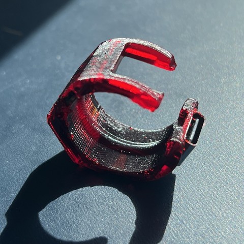
The foldable pcb was a terrible idea that I won’t be doing again, but I got better results on this attempt by first burning the seams with a laser.
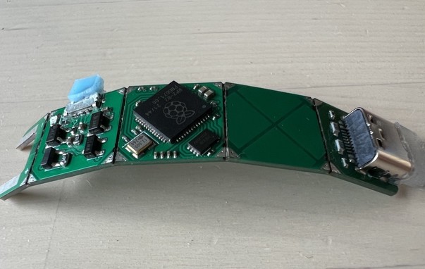
I do like the little 12mm x 12mm modules it's made up from - part of me wants to make a whole bunch of those, with a defined bus of castellated edges. You'd stack them up vertically into tight little volumes of functionality.
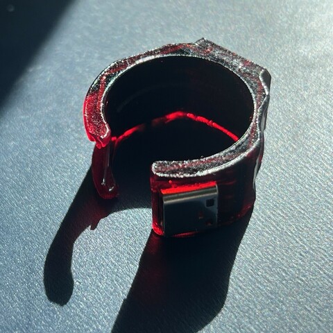
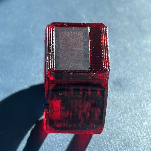
This one survived the process. It's even almost practical.
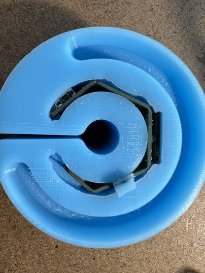
The capacitive touch pad in the ring is just 4 copper pads each connected to a gpio - no external components. A PIO program times how long the pad takes to pull high using the internal pull-up resistors.
@ancientjames it looks great, well done sir.
@ancientjames as a controller this would have made Google Glass useful. Not socially acceptable, mind you, but useful.
This worked well. The capacitive sensor works by discharging the pad through a resistor and timing how long it takes. Previously I was doing this a few thousand times in a loop and returning the accumulated time. Here I'm doing it the other way round - spending a fixed time in the loop, and counting how many charge / discharge cycles it can do. My aim was to make it easier to tune the sample period, but it turns out noticeably smoother and less noisy this way too.
I put the PIO program for this on github: https://github.com/AncientJames/jtouch

@ancientjames this is awesome! I will definitely be cribbing some of your PIO tricks now that I understand a bit how that stuff works
@todbot Apparently it's PIO capsense day!
@ancientjames why does the video have a slightly stop-motion look about it?
@forelioned I think it's just the way my finger sticks a bit on the drawing pins, so it looks jerky.
@ancientjames also one of the frames appears brighter than the others, adding to a film shot like effect.
@ancientjames @Workshopshed oooo that’s really nice
@ancientjames ooo! I'd love to use this as an input device like the ibm nipple 😍
@ancientjames Ooh, I love this way of detecting touch position with capacitive touch! I've been working on a thing that uses capacitive touch, but I have large unbroken areas of copper leaf on a surface that detect touch, and I was trying to figure out a way to detect movement. The main problem with your approach for my use case is it requires multiple GPIOs for one touch area, and I'm trying to detect 10 different touch areas. 🙂
@owengoss There's all sorts of interesting ways to interleave the pads to reduce the number of sensor channels you need. (I'd like to try the 'duplexed slider' here https://www.silabs.com/documents/public/application-notes/AN0040.pdf because it's such a neat approach)
@ancientjames very cool! That looks like a handy resource, thanks for sharing. I’ve just sort of been fumbling my way through things so far. Probably a good idea to read some things. 😅
@owengoss some of the stuff I’ve read on layout requirements, if I’d read it before I did my first stud-touch, would have convinced me that shape was never going to work and I shouldn’t bother. So there’s that.
@owengoss I was thinking about this in the shower - if you restrict it to one finger at a time you can have 10 individual trackpads using only 5 GPIOs.
Each area needs 3 pads to triangulate the position, and each area needs a different set of 3 to distinguish between them.
(5 choose 3) = 10.
I'm sure this isn't actually what you're going for (the fact that you want 10 areas implies you want to use all your fingers), but I was surprised at how efficient the result was.
@ancientjames ah yeah, that’s cool! But yes, I’m trying to support multiple touches (currently I limit it to 4 at once in the software). I’ve been working on a musical instrument of sorts, so it needs to support the multiple touches. I keep thinking it would be cool if each note pad could also detect position on the pad somehow. But maybe that’s asking too much. 😉
@ancientjames This would make an awesome track-point for a mouse!
@ancientjames that’s so smart I love it!
@ancientjames that's very cool. I didn't know it was a thing.
@ancientjames such a cool solution 🔥
@ancientjames Oh that is beautifully elegant! 👏
A while ago I used vaguely similar sensors to make an ugly touch paddle (for a radio transmitter). In addition to the digital logic though, I'm now slightly embarrassed to admit that mine also requires four transistors and an analogue comparator. If I ever build another, next time I'll try it your way first!

@ancientjames
Wow, amazing work.
Would be nice to use it as presenter with BT-HID, countdown-timer at the display, vibration feedback and built in laser pointer. But I guess there is not enough space for all these features.
@Pixtxa definitely needs a laser.
@ancientjames omg this is amazing, i desperately need this futuristic fidget toy
@ancientjames
I need this in my life.
And a second one to somehow attach to my glasses.
@ancientjames
with this ring, i ddqd
with this ring, i ddqd
@forelioned yelling down the hallway HEY GUYS WE FOUND A COOL THING COME HERE YOU GOTTA CHECK THIS OUT
@ddr I just know how much they like DOOM on things, and a ring is a thing on which hitherto DOOM has not run. Also, I have been watching @ancientjames progress on this and to see the finished thing is really cool.
@forelioned I'm pretty much in the same boat here. It's meant from the heart, it really is!
Cool people, all around. :)
Cool! But do consider a range of different colours for those who might want to wear a few at the same time 😊
@ancientjames Behold! The Ring of Doom.