If I make another one, I'm going to change pretty much everything except the colour.
This build was a bit of a washout overall, but since the boards are made up of distinct modules connected by wide traces it’s very easy to break it down and reuse bits. Here’s the usb segment & battery charger segment from one of the casualties charging a little Lego clip-on battery.
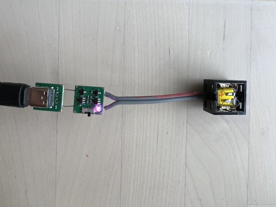
The first two boards from this batch powered up just fine. The next one was dead, and I thought maybe I saw smoke? The next one let the smoke out immediately. I stopped plugging them in after that while I tracked down what was going on. It turns out that for one of the 100K pull down resistors I'd actually ordered 1Ω.
The nice thing about 1 Ohm resistors is it makes the maths very easy when you're working out how badly you cocked up.
This one survived the process. It's even almost practical.
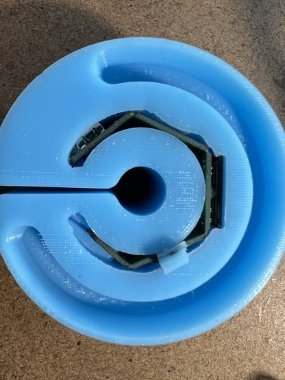
The capacitive touch pad in the ring is just 4 copper pads each connected to a gpio - no external components. A PIO program times how long the pad takes to pull high using the internal pull-up resistors.
@ancientjames Oh that is beautifully elegant! 👏
A while ago I used vaguely similar sensors to make an ugly touch paddle (for a radio transmitter). In addition to the digital logic though, I'm now slightly embarrassed to admit that mine also requires four transistors and an analogue comparator. If I ever build another, next time I'll try it your way first!