Putting it all together
https://blog.narf.ssji.net/2025/02/15/putting-it-all-together/
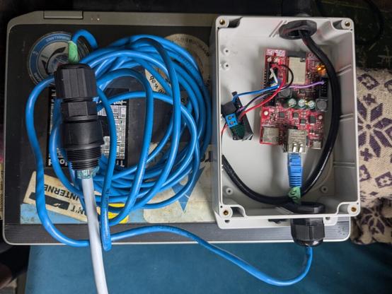
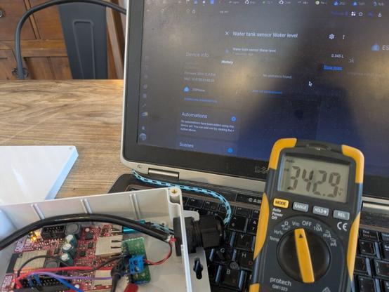
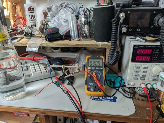
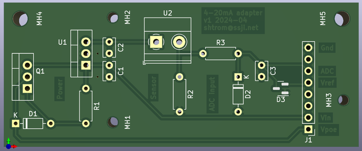
I’m finally putting the water tank sensor together for a test
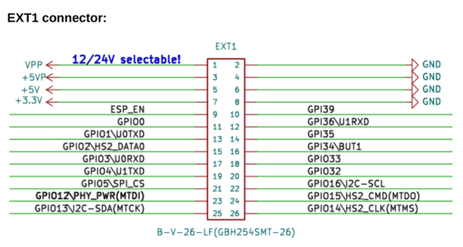
PIN 35 on the ESP32-POE(2) is not Vcc, but the battery level, when a jumper is in place. Rather than putting the jumper, I created a short cable from the 3.3V pin to pin 35. It’s at 3.14V when powered over Ethernet.
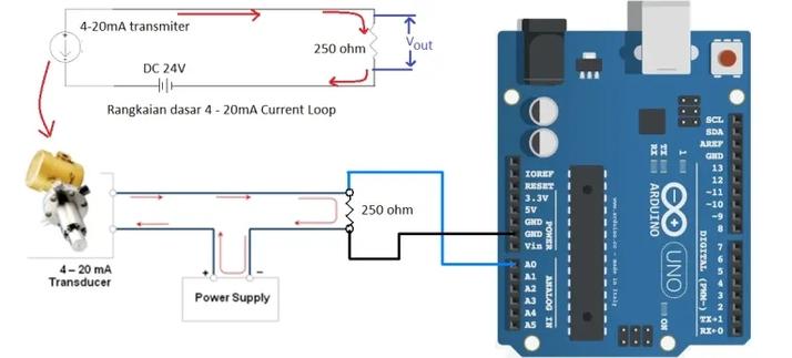
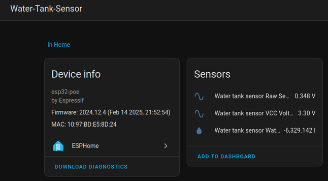
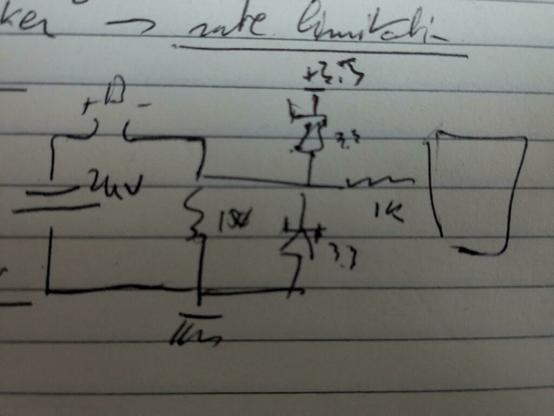
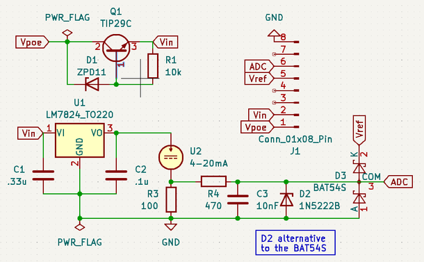
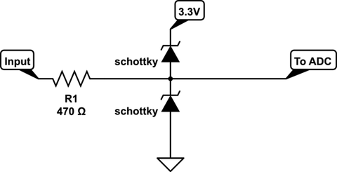
the adc needs attenuation: auto, which works pretty well for both VCC and the current loop sensing resistor (the default is 0dB, which doesn’t)
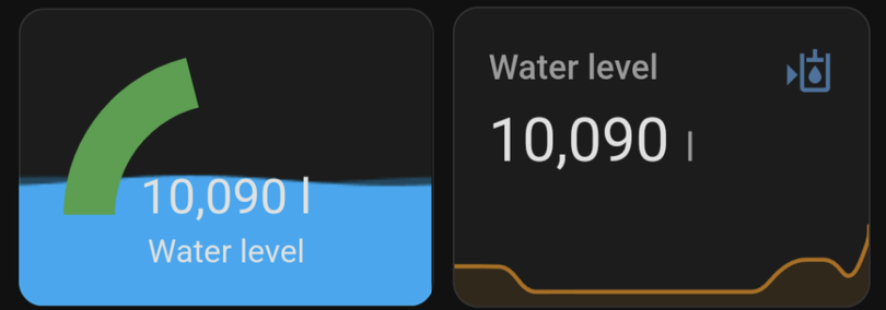
Found a nice Lovelace card for Home Assistant lovelace-fluid-level-background-card
Also using icon mdi:hydraulic-oil-level, which seems more telling than the plain mdi:water
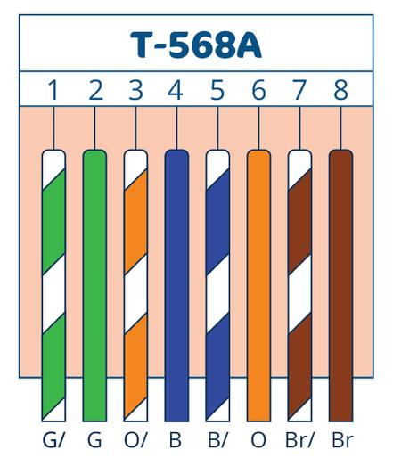
Crimped and patched the CAT6 cable to the water tank. There are two standards for Ethernet connectors, but Australia mostly uses T-568A (green first)
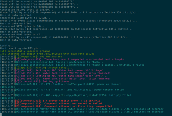
Updated the sensor config to use Ethernet for connectivity, in addition to power (rather than Wi-Fi)
The ESP32-POE2 uses GPIO0 for the clock, same as the first version.
Does DHCP by default, like Wi-Fi did.
Took a leap of faith and OTA’d it. It still work. Pfew.
esphome upload –device water-tank-sensor.example.net water-tank-sensor.yaml
Also moved passwords and related parameters to .gitignored secrets.yaml
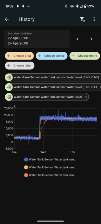
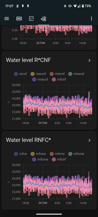
Got some data in! Pretty limited, so far, with one calibration point. Re-enabled the moving average filter to reduce the noise. Now checking with air pressure to see if changes have much of an impact.
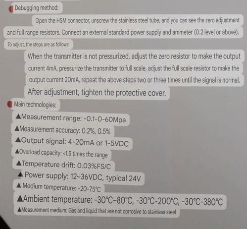
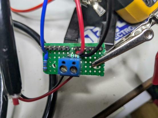
Next steps: add calibration points, maybe add an air pressure sensor if needed, finish the PCB as a generic base for current loop sensors.
[…]
#ESP32 #ESPHome #HomeAssistant #waterTankSensor